
Mesh placement machine and mesh placement method

A technology of mesh and frame, which is applied in the field of mesh placement machine and mesh placement, can solve the problems of inability to flip mesh and adjust mesh, and achieve the effects of ensuring accuracy, improving accuracy, and improving production efficiency

Pending Publication Date: 2020-05-08
ANHUI KEDA IND CO LTD
View PDF2 Cites 5 Cited by
  • Summary
  • Abstract
  • Description
  • Claims
  • Application Information

AI Technical Summary

Problems solved by technology

[0007] Aiming at the problem that the existing mesh cages cannot be efficiently turned over and the distance between the meshes stacked together is adjusted during the production of the existing building steel mesh cages, the present invention provides a mesh placement machine that can automatically place the mesh The stacked meshes are clamped and flipped and the distance between the two meshes is adjusted, and then sent to the cage preparation device for the production of the cages, which effectively improves the production efficiency of the cages

Method used


Image

  • Mesh placement machine and mesh placement method
  • Mesh placement machine and mesh placement method
  • Mesh placement machine and mesh placement method

Examples


Embodiment 1

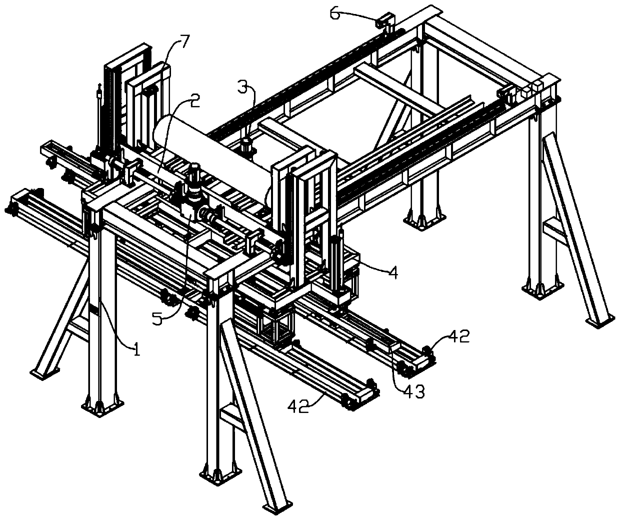
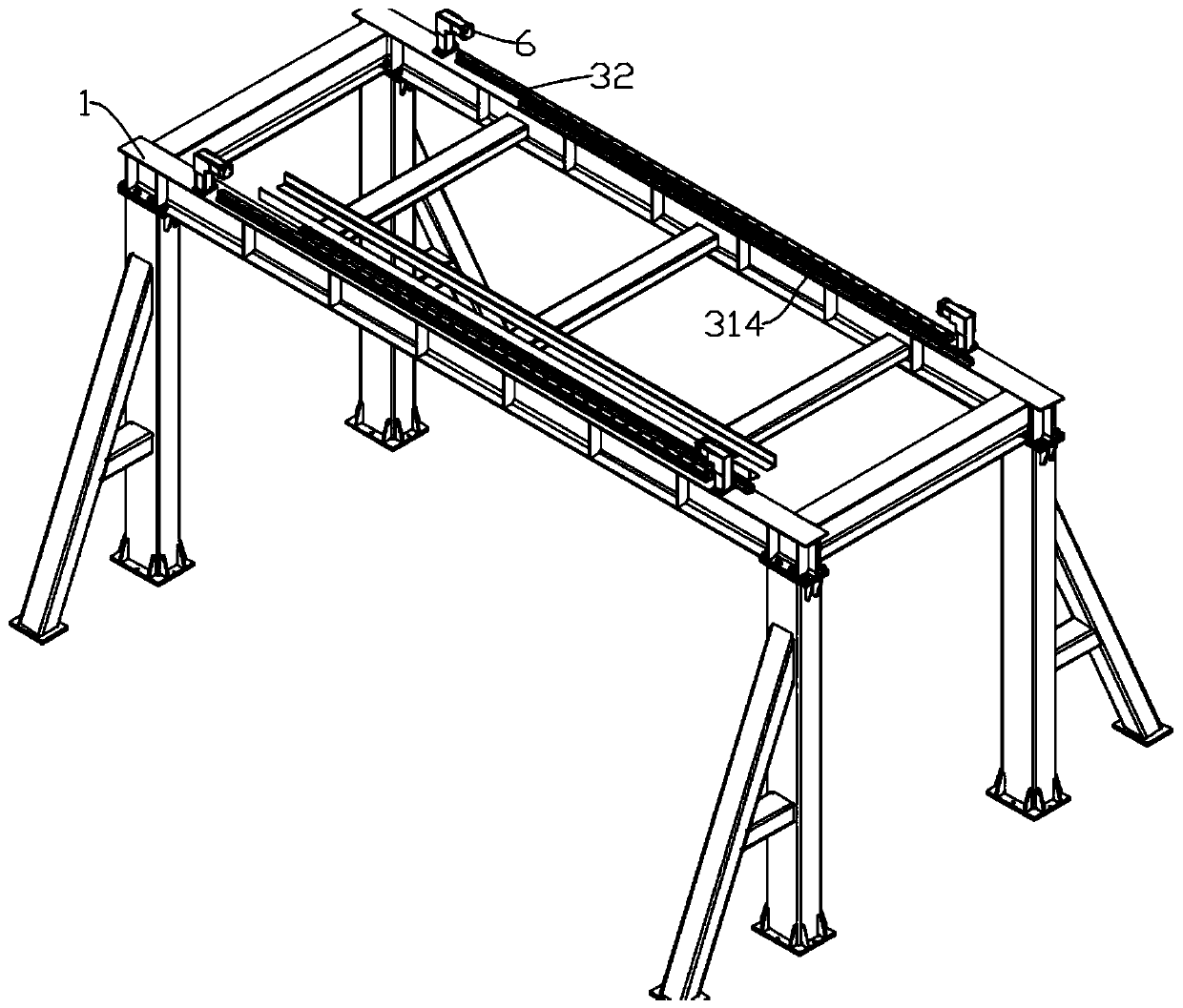
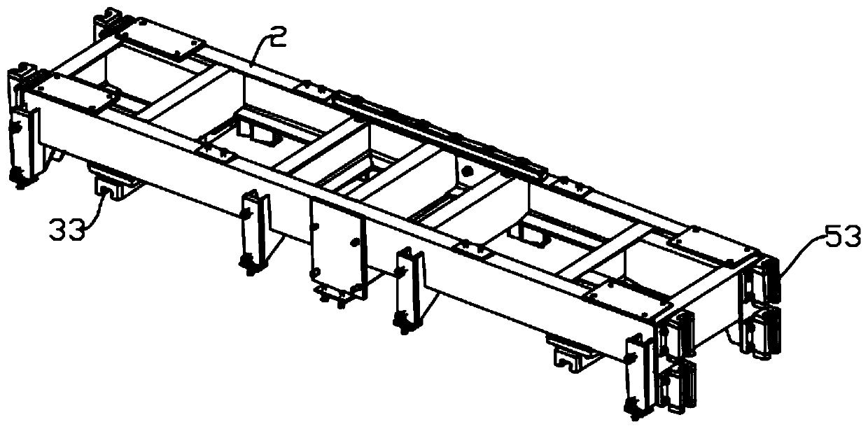
[0059] Such as figure 1 As shown, a mesh placing machine is used for clamping the steel mesh and sending the mesh into the fixing device, which mainly includes a frame 1, a car body 2, a horizontal driving device 3, a mesh picking device 4 and a vertical Direct Drive 5. Wherein, frame 1 is used as the installation main body of each device of the mesh placement machine, and is a rectangular frame structure, and a supporting column is respectively installed below the four corners of the rectangular frame. The car body 2 is a rectangular frame, which is installed on the frame 1 and is used to drive the mesh clamping device 4 to move. The mesh clamping device 4 is installed on the car body 2 for clamping the mesh. The horizontal driving device 3 is used to drive the car body 2 to move in the horizontal direction, and the vertical driving device 5 is used to drive the mesh clamping device 4 to lift. The specific structure and working principle of each device will be described in...

Embodiment 2

[0073] A method for placing mesh, adopting the mesh placing machine of embodiment 1 to place the mesh, the specific process is as follows.

[0074] 1. Before starting, the horizontal driving device 3 drives the car body 2 to move to the top of two adjacent piles of mesh, and the mesh is in a stacked state, and then, as Figure 10 As shown, the vertical driving device 5 works, drives the mesh clamping device 4 to descend to the mesh stacking position, and the flipping grippers 422 of the two flipping fixtures 42 are clamped to clamp a mesh respectively.

[0075] Two, such as Figure 11 As shown, after the vertical driving device 5 drives the mesh clamping device 4 to rise, the turning mechanism drives the turning fixture 42 to rotate until the mesh is in a vertical state. In this embodiment, the mesh is turned 90° inwardly. Then the drive cylinder 1 424 is retracted, and the overturning fixture 42 is sent to the designated position. In this embodiment, two mesh sheets are resp...


PUM


Abstract

The invention discloses a mesh placement machine and a mesh placement method, and belongs to the field of mesh cage production. The placement machine includes a rack, a vehicle body mounted on the rack, a horizontal driving device for driving the vehicle body to move in the horizontal direction, a mesh clamping device and a vertical driving device, the mesh clamping device can clamp meshes, overturn the meshes by 90 degrees and convey the meshes into a mesh placement zone, the meshes horizontally placed and stacked together can be automatically clamped and overturned, the spacing between everytwo meshes is adjusted, then the meshes are conveyed into a fixing zone for mesh cage manufacturing, and the production efficiency of mesh cages is effectively improved. The mesh placement method adopts the mesh placement machine for mesh placement, thus the meshes horizontally placed and stacked together can be efficiently adjusted into the dimensions and positions suitable for mesh cage manufacturing, automatic mesh arrangement is achieved, manual operation is saved, and the production efficiency of the mesh cages is improved.

Description

technical field [0001] The invention belongs to the field of mesh cage production, and more specifically relates to a mesh placement machine and a mesh placement method. Background technique [0002] Building mesh is a new type of building wall material welded by high-quality low-carbon iron wire, steel wire, and stainless steel wire. It can replace brick walls for various load-bearing walls, non-load-bearing walls, balconies, etc. By pouring concrete on the architectural mesh, it can be made into a wall panel, and the architectural mesh inside the concrete acts as a reinforcing rib, making the wall panel easy to form and stronger. The building mesh cage is a derivative of the building mesh. Two parallel mesh sheets are fixed together by several connectors to form a mesh cage structure. The concrete is poured inside, and the concrete wall panel obtained is better than the traditional mesh. Structure, better integrity, stronger and longer service life. However, when two mes...

Claims


Application Information

Patent Timeline
Patent Type & Authority Applications(China)
IPC IPC(8): B21F27/20
CPCB21F27/20
Inventor 吴亚军刘品德余甲峰滕元祥杨梅
Owner ANHUI KEDA IND CO LTD
Learn More