Multipoint lateral glue feeding hot nozzle structure and hot runner system

A side-feeding and hot-runner technology, applied in the field of multi-point side-feeding hot nozzle structure and hot runner system, can solve the problems of complex installation structure, large mold shape, large positioning distance, etc., and achieve good strength and material cost. Low, volume-reducing effect

Pending Publication Date: 2020-05-08
SHENZHEN MOLD TIP TECH CO LTD
View PDF0 Cites 3 Cited by
  • Summary
  • Abstract
  • Description
  • Claims
  • Application Information

AI Technical Summary

Problems solved by technology

[0003] 1. The glue is fed through the hot runner and transferred to the cold runner. This part of the plastic material in the runner always exists. After production, it becomes waste. Usually this type of multi-cavity mold is designed for some small products. , the material wasted by the runner is often more than the product itself. From the perspective of cost, it is very wasteful; because there is a cold runner in the mold, the gate will be broken and the ejection of the runner will be considered. Then the ranking distance between products is also very large;
[0004] 2. In the traditional side-entry hot nozzle (the structure of twisting the nozzle core 11, nozzle head and nozzle body 12 on both sides of the square heating block), the space of all the cavities needs to be enlarged, which will lead to a very large shape of the final mold;
[0005] 3. The installation structure between the existing side-entry hot nozzle and the opening frame 13 is complicated, and it is inconvenient to disassemble

Method used


Image

  • Multipoint lateral glue feeding hot nozzle structure and hot runner system
  • Multipoint lateral glue feeding hot nozzle structure and hot runner system
  • Multipoint lateral glue feeding hot nozzle structure and hot runner system

Examples


Embodiment Construction

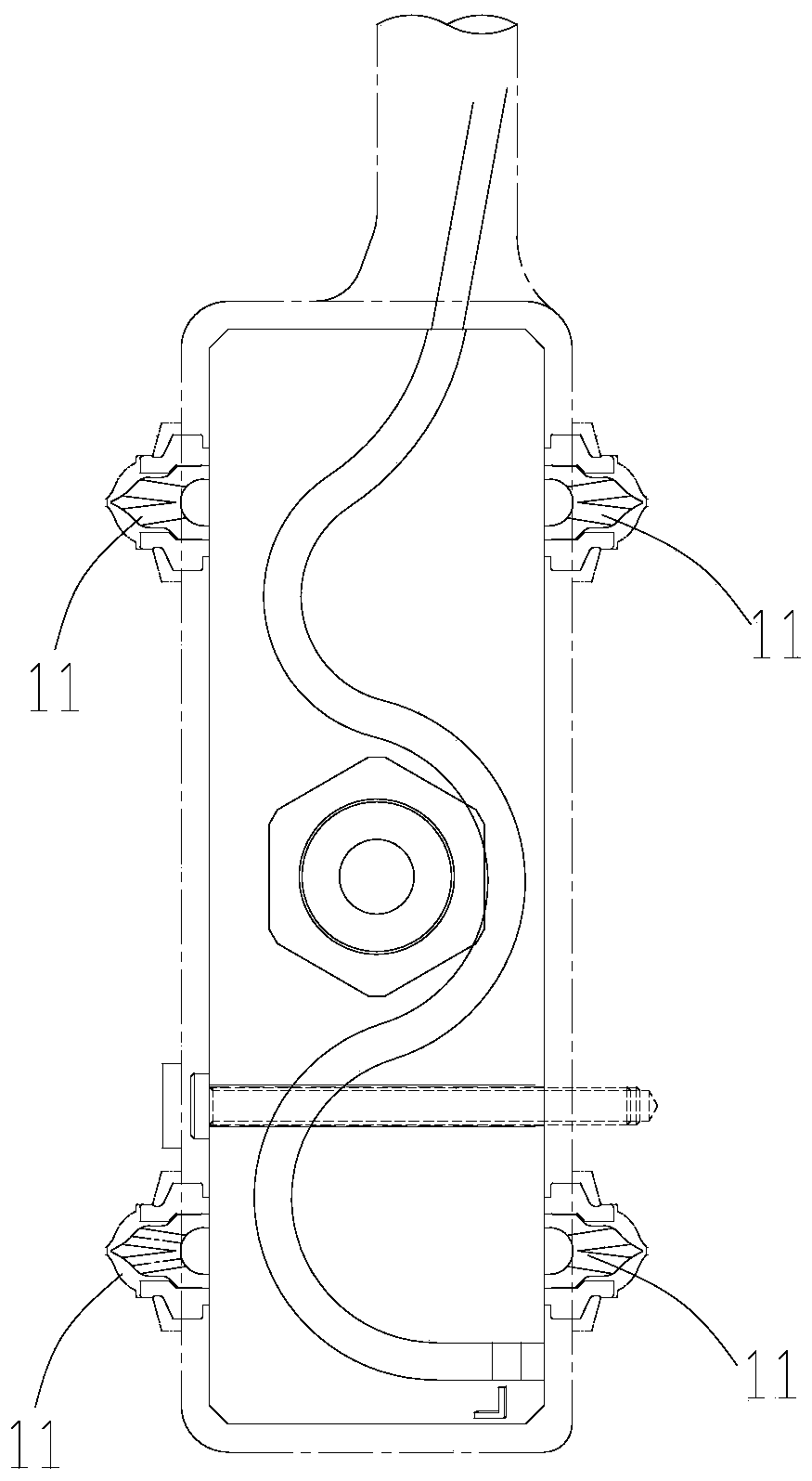
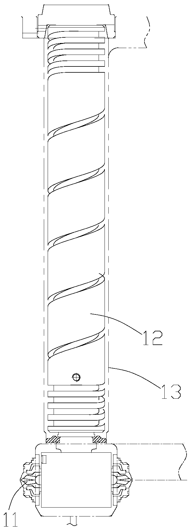
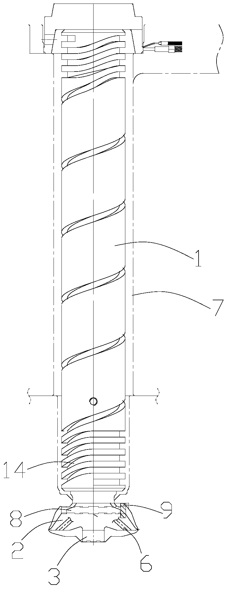
[0033] Below, the present invention will be further described in conjunction with the accompanying drawings and specific implementation methods. It should be noted that, under the premise of not conflicting, the various embodiments described below or the technical features can be combined arbitrarily to form new embodiments. .

[0034] In describing the present invention, it is to be understood that the terms "upper", "lower", "front", "rear", "left", "right", "horizontal", "vertical", "top", The orientation or positional relationship indicated by "outside" is based on the orientation or positional relationship shown in the drawings, which is only for the convenience of describing the present invention and simplifying the description, rather than indicating or implying that the referred device or element must have a specific orientation, are constructed and operate in a particular orientation and therefore are not to be construed as limitations of the invention. In addition, ...


PUM


Abstract

The invention discloses a multipoint lateral glue feeding hot nozzle structure, which comprises a hot nozzle body and a nozzle core, wherein the nozzle core is arranged on one end of the hot nozzle body and is of a horn shape; a plurality of nozzle tips are arranged in the circumferential direction of the nozzle core; the bottom of each nozzle tip is independently provided with a glue inlet; and alateral glue inlet is arranged between any two adjacent nozzle tips. The invention also discloses a hot runner system, which comprises a mould, a hot nozzle open frame and the above multipoint lateral glue feeding hot nozzle structure, wherein the mould comprises a front mould and a rear mould, and the front mould and the rear mould are mutually matched; the hot nozzle open frame is arranged on the front mould; a cavity is formed in the hot nozzle open frame; and the multipoint lateral glue feeding hot nozzle structure is arranged in the cavity and comprises the hot nozzle body and the nozzlecore, and the hot nozzle body, the nozzle core and the hot nozzle open frame are matched. The invention has a simple structure, material cost can be lowered, the volume of the mould is reduced, and the invention is favorable for improving the appearance sense of beauty of a product.

Description

technical field [0001] The invention relates to the technical field of hot runners, in particular to a multi-point side glue hot nozzle structure and a hot runner system. Background technique [0002] In the existing multi-cavity hot runner system for small products, in order to meet the requirements of the number of cavities, such as figure 1 and figure 2 As shown, it is usually realized by adopting the structure of hot runner to cold runner or twisting the nozzle core 11 and the nozzle head on both sides of a large square heating block. This structure has the following problems: [0003] 1. The glue is fed through the hot runner and then transferred to the cold runner. This part of the plastic material in the runner always exists. After production, it becomes waste. Usually this type of multi-cavity mold is designed for some small products. , the material wasted by the runner is often more than the product itself. From the perspective of cost, it is very wasteful; beca...

Claims


Application Information

Patent Timeline
IPC IPC(8): B29C45/27
CPCB29C45/27B29C45/278
Inventor 董鹏鹏贺立明王艳云屈琴许海霞
Owner SHENZHEN MOLD TIP TECH CO LTD
Why Eureka
Try Eureka