A building water storage and discarding device

A technology for buildings and lifting water tanks, applied in water supply devices, drinking water devices, buildings, etc., can solve problems such as troublesome automatic control, pollution, complex structure of the waste flow system, etc., and achieve the effect of pure water quality and convenient and refined actions

Inactive Publication Date: 2020-09-04
NANJING LISHUI HIGH-TECH VENTURE CAPITAL MANAGEMENT CO LTD
View PDF4 Cites 0 Cited by
  • Summary
  • Abstract
  • Description
  • Claims
  • Application Information

AI Technical Summary

Problems solved by technology

Due to the intensification of pollution, the pollution caused by rainwater runoff is relatively serious, especially the scour effect of the initial rainwater on the ground, so that the initial rainwater cannot be directly used after simple filtration and sedimentation; to realize the recycling of rainwater resources, the pollution of the initial runoff must be severely polluted The rainwater is discarded and treated. At present, the initial rainwater runoff is mostly intercepted by the interception pipe network system, which uses the interception pipe network system to intercept the initial rainwater to the sewage pipe network and send it to the sewage treatment plant for purification. Rainwater pollution is relatively light, and after simple treatment, it is directly discharged into natural water bodies; the initial rainwater abandonment facility is to abandon the initial rainwater flow, and the current initial rainwater abandonment facility has the following disadvantages: the abandonment system has a complex structure and is difficult to operate and maintain Large; rainwater drainage equipment is easy to block; automatic control is troublesome

Method used


Image

  • A building water storage and discarding device
  • A building water storage and discarding device
  • A building water storage and discarding device

Examples


Embodiment Construction

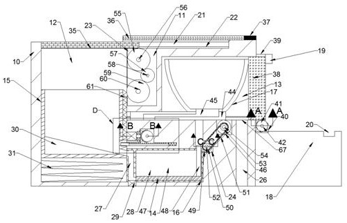
[0018] Combine below Figure 1-5 The present invention is described in detail, and for convenience of description, the orientations mentioned below are now stipulated as follows: figure 1 The up, down, left, right, front and back directions of the projection relationship itself are consistent.

[0019] refer to Figure 1-5 According to an embodiment of the present invention, a water storage and discarding device for a building includes a fuselage 10, the fuselage 10 includes a lifting cavity 12 with an upward opening, and a lifting cavity 12 that can slide up and down is provided in the lifting cavity 12. Water tank 15, a spring 31 is fixed between the lifting water tank 15 and the lower wall of the lifting chamber 12, a detent groove 32 is provided on the right side of the lifting water tank 15, and a detent groove 32 is provided on the right side of the detent groove 32. A bayonet pin 33 that can be inserted into it so as to lock the lifting water tank 15 in place, a gear ...


PUM


Abstract

The invention discloses a building stored-water discharge device. The building stored-water discharge device comprises a machine body, the machine body internally comprises a lifting cavity with an upward opening, the lifting cavity is internally provided with a lifting water tank capable of sliding up and down, a spring is fixedly arranged between the lifting water tank and the lower wall of thelifting cavity, a clamping pin groove is formed in the right side of the lifting water tank, and a clamping pin capable of stretching into the clamping pin groove and thus clamping the position of thelifting water tank is arranged on the right side of the clamping pin groove. According to the building stored-water discharge device, a rainwater receiving tank for collecting rainwater can be put out for storage according to the corresponding weather; and meanwhile, a first wave of seriously-polluted rainwater during raining can be discharged, the later clean rainwater is collected, thus it is ensured that the water quality in a reservoir is pure, and the overall movement is convenient, fast and concise.

Description

technical field [0001] The invention relates to the technical field of rainwater treatment, in particular to a water storage and waste flow device for buildings. Background technique [0002] In recent years, with the deterioration of the natural environment and the shortage of water resources, the collection and utilization of rainwater has become particularly important. Due to the intensification of pollution, the pollution caused by rainwater runoff is relatively serious, especially the scour effect of the initial rainwater on the ground, so that the initial rainwater cannot be directly used after simple filtration and sedimentation; to realize the recycling of rainwater resources, the pollution of the initial runoff must be severely polluted The rainwater is discarded and treated. At present, the initial rainwater runoff is mostly intercepted by the interception pipe network system, which uses the interception pipe network system to intercept the initial rainwater to the...

Claims


Application Information

Patent Timeline
Patent Type & Authority Patents(China)
IPC IPC(8): E03B3/02E03B11/00
CPCE03B3/02E03B11/00Y02A20/108
Inventor 周宏达
Owner NANJING LISHUI HIGH-TECH VENTURE CAPITAL MANAGEMENT CO LTD
Why Eureka
Try Eureka