Hydraulic valve for camshaft phaser adjusting

A phaser and camshaft technology, applied in the direction of valve devices, machines/engines, non-mechanical actuated valves, etc., can solve the problems of unsatisfactory emissions, fuel consumption and power, etc., and achieve the effect of increasing the locking and unlocking functions

Active Publication Date: 2020-05-08
JAPHL POWERTRAIN SYST
View PDF6 Cites 0 Cited by
  • Summary
  • Abstract
  • Description
  • Claims
  • Application Information

AI Technical Summary

Problems solved by technology

However, the existing side-mounted or mid-mounted hydraulic valves can only achieve one-way adjustment of the camshaft in advance or lag, which cannot meet the increasingly stringent requirements for emissions, fuel consumption, and power.

Method used


Image

  • Hydraulic valve for camshaft phaser adjusting
  • Hydraulic valve for camshaft phaser adjusting

Examples


Embodiment Construction

[0020] Below with reference to the accompanying drawings, through the description of the embodiments, the specific embodiments of the present invention, such as the shape, structure, mutual position and connection relationship between the various parts, the role and working principle of the various parts, etc., will be further described. Detailed instructions:

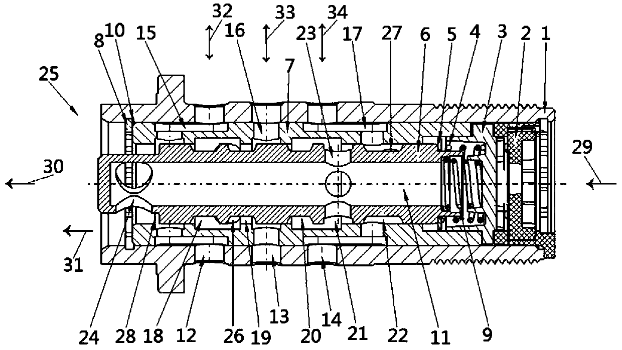
[0021] as attached figure 1 As shown, the present invention is a hydraulic valve for adjusting a camshaft phaser, including a valve body 1, a valve sleeve 7 is set in the valve body 1, a valve core 6 is movably arranged in the valve sleeve 7, and one end of the valve body 1 The hydraulic oil inlet P29 is set, and the other end of the valve body 1 is set with the hydraulic oil outlet T30. Ⅳ21, spool discharge hole Ⅰ23, hydraulic oil outlet T30 are set in a connected structure, valve body oil circuit interface L34, valve sleeve guide chamber Ⅲ17, spool ring groove Ⅳ21, spool discharge hole Ⅰ23, hydraulic oil When the o...


PUM


Abstract

The invention provides a hydraulic valve for camshaft phaser adjusting, and belongs to the technical field of engine variable valve timing. When a valve element (6) is located at the end close to a hydraulic oil outlet T (30), a valve body oil way connector L (34), a valve sleeve diversion cavity III (17), a valve element circular groove IV (21), a valve element leak-off hole I (23) and the hydraulic oil outlet T (30) are arranged to be of a structure in a communication state, and when the valve body oil way connector L (34), the valve sleeve diversion cavity III (17), the valve element circular groove IV (21), the valve element leak-off hole I (23) and the hydraulic oil outlet T (30) are in the communication state, hydraulic oil is arranged to be of a structure capable of pushing a phaserlock pin to lock a camshaft phaser in the initial position. According to the hydraulic valve for camshaft phaser adjusting, phaser advance and lagging bidirectional adjusting can be achieved conveniently and reliably, the valve overlap angle adjusting range is widened, the value of the valve overlap angle is optimized, engine oil consumption and hazardous substance emission are reduced, and the overall performance of an engine is improved.

Description

technical field [0001] The invention belongs to the technical field of engine variable valve timing, and more specifically relates to a hydraulic valve for adjusting a camshaft phaser. Background technique [0002] In the variable valve timing technology (VVT) of the automobile engine, it is necessary to use the camshaft phaser to adjust the hydraulic valve. The working principle of the hydraulic valve adjusted by the camshaft phaser is as follows: the spool of the hydraulic valve is pushed by the force of the hydraulic oil and moves axially along the valve sleeve of the hydraulic valve. The oil pressure difference between the two chambers can push the camshaft to advance or retard the rotation relative to the crankshaft, so as to realize the adjustment of the engine valve timing and optimize the engine performance index. However, the existing side-mounted or mid-mounted hydraulic valves can only achieve one-way adjustment of the camshaft in advance or lag, which cannot mee...

Claims


Application Information

Patent Timeline
IPC IPC(8): F01L1/344F01L9/02F01L9/10F01L9/40
CPCF01L1/344F01L9/10
Inventor 李果姜倩李后良许亮丁万龙王友安甄子源
Owner JAPHL POWERTRAIN SYST
Why Eureka
Try Eureka