Synchronous scanning circuit system based on PLL and DDS

A synchronous scanning, circuit system technology, applied in the direction of electrical components, automatic power control, etc., can solve the problems of narrow synchronous tracking range, low integration, complex analog oscillator circuit, etc., to reduce the design difficulty, improve the integration, reliability and so on. high sex effect

Inactive Publication Date: 2014-05-07
XI'AN INST OF OPTICS & FINE MECHANICS - CHINESE ACAD OF SCI
View PDF3 Cites 3 Cited by
  • Summary
  • Abstract
  • Description
  • Claims
  • Application Information

AI Technical Summary

Problems solved by technology

[0003] In order to solve the technical problems existing in the background technology, the present invention provides a synchronous scanning circuit sy

Method used


Image

  • Synchronous scanning circuit system based on PLL and DDS
  • Synchronous scanning circuit system based on PLL and DDS
  • Synchronous scanning circuit system based on PLL and DDS

Examples


Embodiment Construction

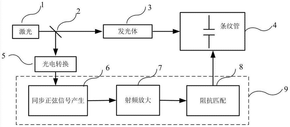
[0017] The invention provides a scanning circuit for a synchronous scanning stripe camera based on PLL and DDS. The specific implementation steps are as follows: 1) The trigger light pulse signal passes through a high-speed photoelectric conversion device to complete photoelectric conversion, and obtains a reference electrical signal with the same frequency as the trigger light pulse. The photoelectric conversion of the trigger light pulse adopts a low-noise photoelectric conversion device. The photoelectric conversion device should be able to respond effectively to the trigger light pulse, and the response bandwidth should be greater than the highest frequency of the highest trigger light pulse.

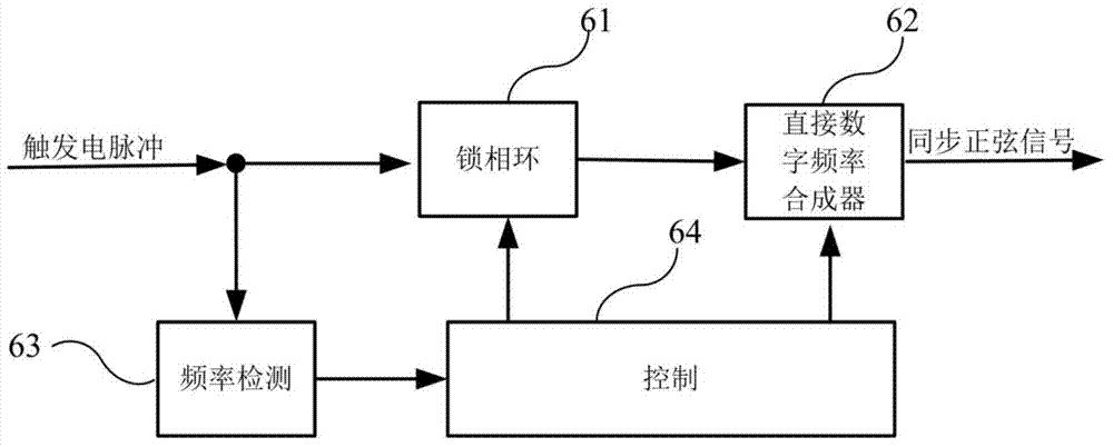
[0018] 2) The reference electrical signal is divided into two paths, one path is used as the input of the frequency detection module 63 to detect the frequency of the trigger signal, and the automatic tracking and locking function of the synchronous sinusoidal signal generation circui...


PUM


Abstract

The present invention provides a synchronous scanning circuit system based on PLL and DDS, which comprises trigger laser and a lens. The trigger laser is divided into two paths by the lens, wherein the optical path of one path of trigger laser is provided with a synchronous scanning strip camera, and the optical path of the other path of trigger laser is provided with a photoelectric converter and a synchronous scanning circuit. A trigger signal is converted to an electric pulse signal through the photoelectric converter and enters the triggering input end of the synchronous scanning circuit. The synchronous scanning circuit based on the PLL and DDS according to the invention mainly settles the following problems in an analog oscillating circuit: complicated structure, low integration degree and narrow synchronous tracking range.

Description

technical field [0001] The invention relates to the technical field of high-speed photography, in particular to a scanning circuit system of a synchronous scanning stripe camera. Background technique [0002] The synchronous scanning circuit system is an important part of the synchronous scanning streak camera, and its functional composition and index performance are directly related to the performance of the synchronous scanning streak camera. The synchronous scanning circuit system mainly provides synchronous and phase-adjustable sinusoidal deflection voltage for the scanning deflection plate. It is generally composed of synchronous sinusoidal signal generation, phase adjustment, radio frequency signal amplification, impedance matching and other functional modules. Synchronous sinusoidal signal generation is synchronous scanning. The key to circuit system design. At present, the synchronous sinusoidal signal generation method commonly used in the world is based on the osc...

Claims


Application Information

Patent Timeline
IPC IPC(8): H03L7/099
Inventor 白永林朱炳利刘百玉王博白晓红秦君军缑永胜杨文正徐鹏
Owner XI'AN INST OF OPTICS & FINE MECHANICS - CHINESE ACAD OF SCI
Why Eureka
Try Eureka