Apparatus and methods for spooled vertebral anchors

a vertebral anchor and appendix technology, applied in the field of concepts of fastening, can solve problems such as general unsuitability for maintaining compressive load

Pending Publication Date: 2021-09-23
ORTHOPEDIATRICS CORP
View PDF5 Cites 3 Cited by
  • Summary
  • Abstract
  • Description
  • Claims
  • Application Information

AI Technical Summary

Benefits of technology

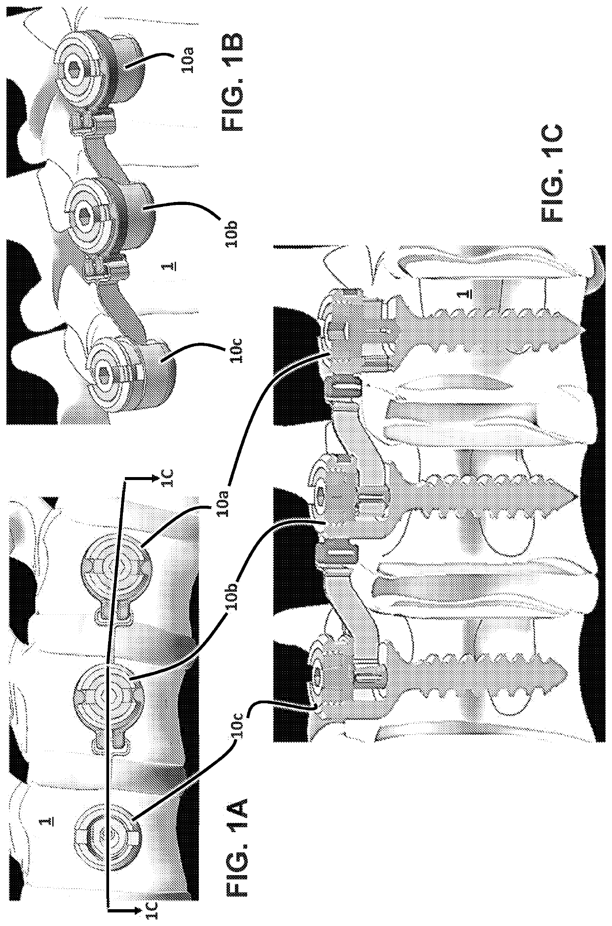
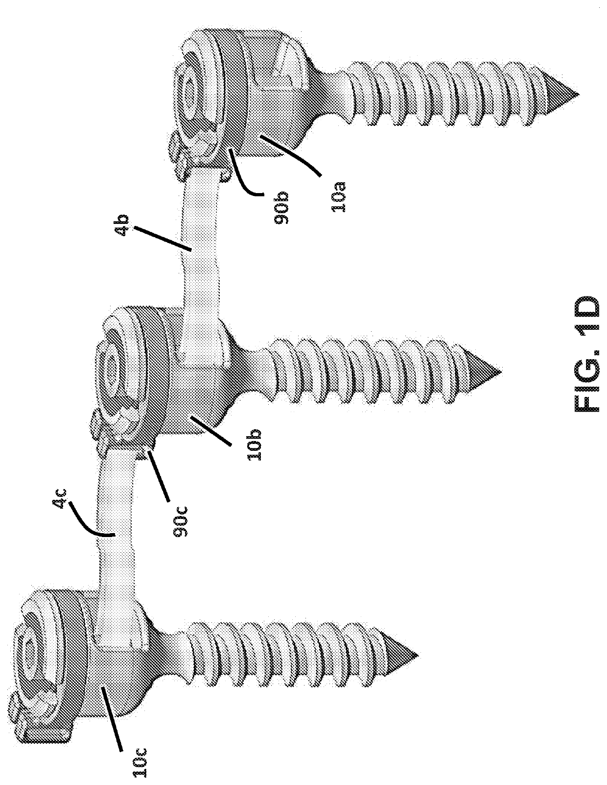
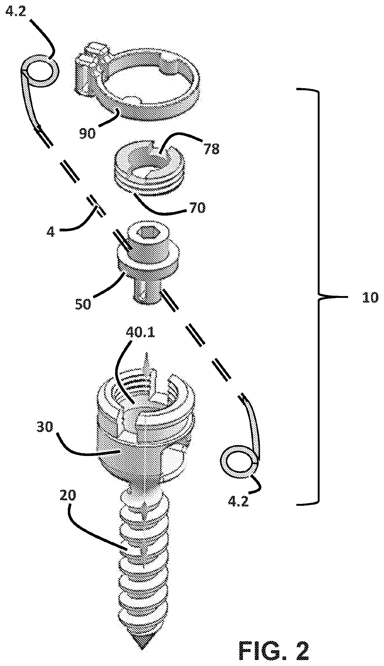
[0014]A spool that is perpendicular to the axis of the fastener. This design substantially mitigates torque balance issues, in that any torque imparted to the screw body from tension on the tether has no tendency to cause the screw body to rotate in the bone.
[0016]The set screw compress against a metal portion of the screw to improve locking function, the axis of the spool can rest in a tapered slot. Without compression, the spool is allowed to “float” at the top of the slot and rotate freely.
[0027]Yet other embodiments of the present invention pertain to the use of a tensioning instrument during surgery to adjust the tension of a flexible member attached to 2 implants. In one embodiment, the tensioner transfers rotational motion to the spool via a gear, such as a bevel gear. In yet another embodiment the tensioner transferring rotational motion to the spool in an axis that is not parallel to the spool. Yet other embodiments include a tensioner having clocking features between the tensioner and implant that allow the set screw to be tightened without spinning the whole implant.
[0028]In yet other embodiments there is a tensioner design that connects to the implant in an “outrigger” fashion for use with an instrument for tightening a set screw (i.e. centerlines of the instruments are not aligned). This allows the Tensioner to fit down a limited size portal (e.g. 15 mm) while maintaining enough space at the end for a bevel gear.

Problems solved by technology

Preferably, the connection if of the type that can sustain a load in tension, but which is generally unsuitable for maintaining a compressive load.

Method used


Image

  • Apparatus and methods for spooled vertebral anchors
  • Apparatus and methods for spooled vertebral anchors
  • Apparatus and methods for spooled vertebral anchors

Examples


Embodiment Construction

[0155]For the purposes of promoting an understanding of the principles of the invention, reference will now be made to the embodiments illustrated in the drawings and specific language will be used to describe the same. It will nevertheless be understood that no limitation of the scope of the invention is thereby intended, such alterations and further modifications in the illustrated device, and such further applications of the principles of the invention as illustrated therein being contemplated as would normally occur to one skilled in the art to which the invention relates. At least one embodiment of the present invention will be described and shown, and this application may show and / or describe other embodiments of the present invention, and further permits the reasonable and logical inference of still other embodiments as would be understood by persons of ordinary skill in the art.

[0156]It is understood that any reference to “the invention” is a reference to an embodiment of a ...


PUM


Abstract

Apparatus and method for dynamic connection between adjacent bones. Various embodiments pertain to a bone anchor that includes a rotatable spool, the spool being configured to place tension on a flexible member, such as a tether, suture, cable, or other. Still further embodiments pertain to tools for interconnecting two bone anchors with a tether.

Description

CROSS REFERENCE TO RELATED APPLICATIONS[0001]This application claims the benefit of priority to U.S. Provisional Patent Application Ser. No. 62 / 873,526, filed Jul. 12, 2019, and U.S. Provisional Patent Application Ser. No. 62 / 716,550, filed Aug. 9, 2018, both of which are incorporated herein by reference.FIELD OF THE INVENTION[0002]Various embodiments of the inventions shown and described herein pertain to various concepts in fastening, and in particular to bone anchors, especially those that place a tensile load between two anchors.SUMMARY OF THE INVENTION[0003]Various anchors are shown herein for providing a flexible connection between adjacent bone anchors. Preferably, the connection if of the type that can sustain a load in tension, but which is generally unsuitable for maintaining a compressive load. Various examples of the flexible connections include sutures, cables, springs, and tethers, including tape, woven tape, braided sutures, and flat braids, as various non-limiting ex...

Claims


Application Information

Patent Timeline
Patent Type & Authority Applications(United States)
IPC IPC(8): A61B17/70
CPCA61B17/7022A61B17/7026A61B2017/00367A61B17/7049A61B17/7019A61B17/8695A61B17/8605A61B17/863A61B17/8869A61B17/842A61B17/7001A61B17/7091A61B17/7044A61B17/809A61B17/7008
Inventor DANIELS, DAVID W.PRYGOSKI, MATTHEWDETLEFSEN, RICHARDTOZAKOGLOU, EVANGELOS
Owner ORTHOPEDIATRICS CORP
Why Eureka
Try Eureka