Quick connecting structure of pipefitting

A technology for connecting structures and pipe fittings, which is applied in the direction of mechanical equipment, couplings, etc., can solve the problems of inability to adapt to pipe fittings, cannot rotate and twist, cumbersome operation, bulky volume, etc., and achieves the effects of small space occupation, simple operation, and small volume

Pending Publication Date: 2020-05-08
CHENGDU AUTO SENSOR TECH CO LTD
View PDF0 Cites 2 Cited by
  • Summary
  • Abstract
  • Description
  • Claims
  • Application Information

AI Technical Summary

Problems solved by technology

[0004] The purpose of the present invention is to propose a quick-connect structure for pipe fittings to solve the problems of cumbersome operation, bulky volume, and inability to adapt to the inability to rotate and twist pipe fittings.

Method used


Image

  • Quick connecting structure of pipefitting
  • Quick connecting structure of pipefitting
  • Quick connecting structure of pipefitting

Examples


Embodiment 1

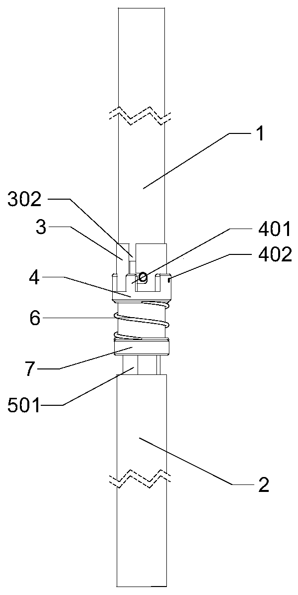
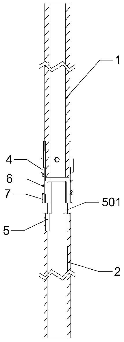
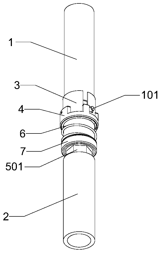
[0031] Such as Figure 1-5 As shown, the present invention is a quick connection structure of pipe fittings, which connects the upper pipe 1 and the lower pipe 2. The part of the upper pipe 1 used for connection is also provided with a raised stud 101, including a slot sleeve 3 and a snap ring 4 And the connection sleeve 5, one end of the connection sleeve 5 is connected with the lower pipe 2, the other end of the connection sleeve 5 is connected with the slot cover 3, the slot cover 3 is provided with a slot 301 and a notch groove 302, the slot cover 3 Through the notch groove 302 and the protruding stud 101 of the upper tube 1, the snap ring 4 is sleeved outside the snap ring 4, and a limit block 401 is also arranged on the snap ring 4, and the snap ring 4 passes through the clip. The slot 301 and the snap ring 4 are fixed in cooperation with each other, and the snap ring 4 limits the protruding stud 101 of the upper tube 1 in the notch slot 302 through the stop block 401 . ...

Embodiment 2

[0034] This embodiment is a further description of the present invention.

[0035] Such as Figure 1-3 As shown, this embodiment is based on Embodiment 1. In a preferred embodiment of the present invention, a spring 6 and a spring retaining ring 7 are also sleeved on the periphery of the card slot sleeve 3, and the spring retaining ring 7 is fixed On the slot sleeve 3 , the spring 6 is arranged between the retaining ring 7 and the snap ring 4 , and the spring 6 abuts against the snap ring 4 . With the above-mentioned structure, the lower end of the spring 6 is positioned and blocked by the retaining ring 7, so that the protruding stud 101 of the upper tube 1 enters from the notch groove 302, and the snap ring 4 moves down along the groove sleeve 3, compressing the spring 6, and After the protruding stud 101 of the tube 1 snaps into the bottom of the notch groove 302, the snap ring 4 will rebound and lock the protruding stud 101 of the upper tube 1 under the action of the spring...

Embodiment 3

[0037] This embodiment is a further description of the present invention.

[0038] This embodiment is based on the above embodiments, and in a preferred embodiment of the present invention, a positioning block 501 is also provided in the middle of the connecting sleeve 5 . With the above-mentioned structure, the positioning block 501 is used to separate the two ends of the connection sleeve 5 and connect with the down tube 2 and the groove sleeve 3 respectively.

[0039] In a preferred embodiment of the present invention, both ends of the connecting sleeve 5 are provided with threads, one end of the connecting sleeve 5 is threaded with the lower pipe 2, and the other end of the connecting sleeve 5 is threaded with the slot sleeve 3 . With the above structure, through the thread pre-connection of the connecting sleeve 5 and the lower pipe 2, it is only necessary to rotate the connecting sleeve 5 without rotating the lower pipe 2; the other end of the connecting sleeve 5 is thr...


PUM


Abstract

The invention discloses a quick connecting structure of a pipefitting. The quick connecting structure comprises an upper pipe and a lower pipe. A protruding stud is also arranged in a part, for connection, of the upper pipe. The protruding stud comprises a slot sleeve, a clamping ring and a connecting sleeve. One end of the connecting sleeve is connected to the lower pipe while the other end of the connecting sleeve is connected to the slot sleeve, a slot and a notch groove are formed in the slot sleeve, the slot sleeve is in fit connection to the protruding stud of the upper pipe through thenotch groove, the clamping ring is arranged outside the slot sleeve in a sleeving manner, a limiting block is also arranged on the clamping ring, the slot sleeve is matched with and fixed to the clamping ring through the slot, and the clamping ring is limited in the notch groove by the protruding stud on the upper pipe through the limiting block. The quick connecting structure is suitable for a condition that the pipefitting cannot rotate to a great extent, is small in size, suitable for a condition that the assembling space between the pipefittings is small and is simple and convenient to operate.

Description

technical field [0001] The invention relates to the field of pipe fitting connection, in particular to a pipe fitting quick connection structure. Background technique [0002] Today's industry is developing rapidly, and various pipe fittings are used, and their connection methods are also diverse. In production applications, it is necessary to quickly and conveniently splice and combine pipe fittings, which requires that the quick-connect joints must have the ability to be fast and easy to operate. . [0003] Traditional pipe joints usually use threaded connections, which are suitable for pipe fittings of various materials and types, and can also be applied with a sealing structure, but the thread cannot adapt to the situation where the pipe fittings cannot be rotated and twisted, and it needs many turns to fix it, and it takes a lot of time to spin. tight, the efficiency is not high, and there is a situation that the thread is easy to fail after loosening. Some pipe fitti...

Claims


Application Information

Patent Timeline
Patent Type & Authority Applications(China)
IPC IPC(8): F16L37/252
CPCF16L37/252
Inventor 李涛叶竹之桑利李新漆小春白鸥黄福芝
Owner CHENGDU AUTO SENSOR TECH CO LTD
Why Eureka
Try Eureka