
Unmanned aerial vehicle atmosphere monitoring equipment

A technology for atmospheric monitoring and drones, applied to unmanned aircraft, motor vehicles, measuring devices, etc., can solve the problem of cumbersome connection between testing equipment and drones, affecting the detection accuracy of testing equipment, and time-consuming and laborious disassembly process To achieve the effect of reducing the number of reciprocating navigation, facilitating storage and transportation, and increasing the sampling range

Pending Publication Date: 2020-05-08
中科赛悟科技(安徽)有限公司
View PDF0 Cites 3 Cited by
  • Summary
  • Abstract
  • Description
  • Claims
  • Application Information

AI Technical Summary

Problems solved by technology

[0002] In recent years, with the rapid development of the industry, the relevant environmental protection departments have increasingly intensified the detection tasks of the atmospheric environment, and put forward higher requirements for the response speed and detection accuracy of the detection equipment. Therefore, many new air detection methods have emerged, among which UAV detection equipment is one of the detection methods with rapid development speed. However, the existing UAV detection equipment still has the following defects: first, it is often necessary to disassemble the detection equipment and the UAV before and after use, and The connection between the existing detection equipment and the drone is cumbersome, and the disassembly process is time-consuming and laborious; second, the gas sampling port of the existing detection equipment is relatively close to the rotor of the drone, which is easily disturbed by the rotor airflow, which affects the detection accuracy of the detection equipment

Method used


Image

  • Unmanned aerial vehicle atmosphere monitoring equipment
  • Unmanned aerial vehicle atmosphere monitoring equipment
  • Unmanned aerial vehicle atmosphere monitoring equipment

Examples


Embodiment Construction

[0024] In order to make the objects and advantages of the present invention clearer, the present invention will be specifically described below in conjunction with examples. It should be understood that the following words are only used to describe one or several specific implementation modes of the present invention, and do not strictly limit the protection scope of the specific claims of the present invention.

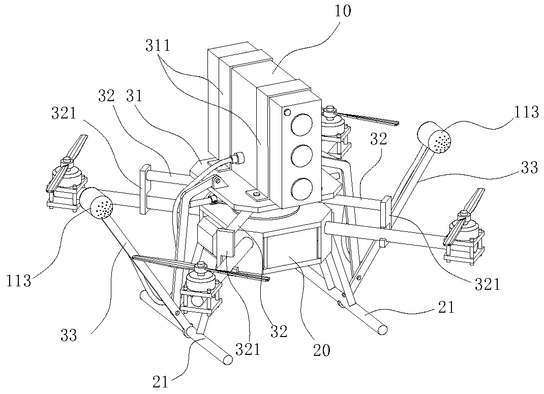
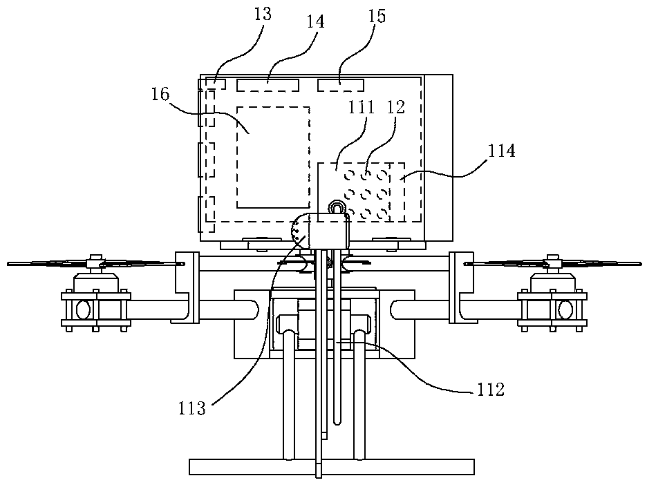
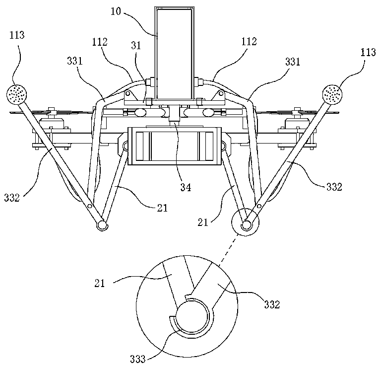
[0025] Such as Figure 1-8 Shown, a kind of unmanned aerial vehicle atmospheric monitoring equipment, comprises detection equipment 10, four-rotor unmanned aircraft 20 aircrafts, and is used to connect the installation bracket of detection equipment 10 and four-rotor unmanned aircrafts 20 aircrafts; Said detection equipment 10 comprises housing , the housing is provided with a sampling assembly, an air detection sensor 12, a video capture module 13, a GPS positioning module 14, a signal wireless transmission module 15 and a power supply module 16; , the air detectio...


PUM


Abstract

The invention belongs to the technical field of atmospheric environment monitoring, and particularly relates to unmanned aerial vehicle atmospheric monitoring equipment, which comprises detection equipment, a quadrotor unmanned aerial vehicle and a mounting bracket for connecting the detection equipment and the quadrotor unmanned aerial vehicle, the detection equipment comprises a shell, and a sampling assembly, an air detection sensor, a video capture module, a GPS positioning module, a signal wireless transmission module and a power supply module are arranged in the shell. Rapid disassemblyand assembly of the detection equipment and the unmanned aerial vehicle are realized through the mounting bracket, and a air sampling port of the sampling assembly is far away from a rotor wing of theunmanned aerial vehicle through an extension arm, so that interference of airflow generated by the rotor wing to detection data is avoided; besides, when the extension arm is unfolded, the sampling range of the detection equipment can be enlarged, the reciprocating navigation frequency of the unmanned aerial vehicle is reduced, the detection efficiency is improved, and the extension arm is convenient for overall storage and transportation of the unmanned aerial vehicle detection equipment in a folded state.

Description

technical field [0001] The invention belongs to the technical field of atmospheric environment monitoring, and in particular relates to an unmanned aerial vehicle atmospheric monitoring device. Background technique [0002] In recent years, with the rapid development of the industry, the relevant environmental protection departments have increasingly intensified the detection tasks of the atmospheric environment, and put forward higher requirements for the response speed and detection accuracy of the detection equipment. Therefore, many new air detection methods have emerged, among which UAV detection equipment is one of the detection methods with rapid development speed. However, the existing UAV detection equipment still has the following defects: first, it is often necessary to disassemble the detection equipment and the UAV before and after use, and The connection between the existing detection equipment and the drone is cumbersome, and the disassembly process is time-co...

Claims


Application Information

Patent Timeline
Patent Type & Authority Applications(China)
IPC IPC(8): G01N33/00B64C39/02
CPCG01N33/0009B64C39/02B64U10/10B64U2101/00
Inventor 解娟章樑张放张潇小
Owner 中科赛悟科技(安徽)有限公司
Learn More