Switch electric leakage detection device

A leakage detection and leakage detector technology, applied in circuit breaker testing, short-circuit testing, etc., can solve the problems of inconvenient installation, inability to detect multiple places, danger, etc., and achieve the effect of easy installation

Inactive Publication Date: 2020-05-08
淮安宝盛德电子有限公司
View PDF0 Cites 2 Cited by
  • Summary
  • Abstract
  • Description
  • Claims
  • Application Information

AI Technical Summary

Problems solved by technology

There is a certain potential difference between the electrical shell and the live wire of the mains for some reason, and there will be a certain potential difference between the ground and the leakage will occur. The existing device detects the leakage by touching the charged body with an electric pen. If the neon bulb lights up It will go off immediately, which proves that the charged body is charged with static electricity. If it is always on, there is no doubt that there is a leakage. In this way, if the detection hand accidentally touches the charged body in the case of leakage, it will cause the detection personnel to get an electric shock. At the same time, the existing The installation of the detection device is unstable or inconvenient to install, and the existing devices or methods can only detect one place at a time, and cannot detect multiple places

Method used


Image

  • Switch electric leakage detection device
  • Switch electric leakage detection device
  • Switch electric leakage detection device

Examples


Embodiment Construction

[0017] The following will clearly and completely describe the technical solutions in the embodiments of the present invention with reference to the accompanying drawings in the embodiments of the present invention. Obviously, the described embodiments are only some, not all, embodiments of the present invention. Based on the embodiments of the present invention, all other embodiments obtained by persons of ordinary skill in the art without making creative efforts belong to the protection scope of the present invention.

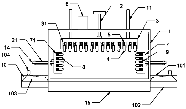
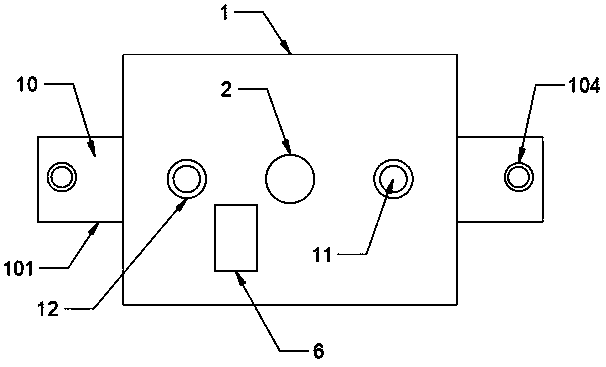
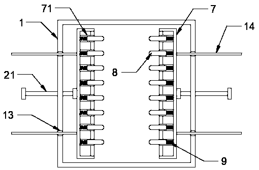
[0018] see Figure 1-3 , the present invention provides a technical solution: a switch leakage detection device, including a housing 1, the upper end of the inner side of the housing 1 is movably mounted with a first screw 2 through threads, and the inner side of the first screw 2 of the housing 1 The lower end is movably installed with a first contact plate 3 through a bearing, and the lower end surface of the first contact plate 3 is provided with a pluralit...


PUM


Abstract

The invention discloses a switch electric leakage detection device. The device includes a shell, a first screw rod is movably mounted at the upper end on the inner side of the shell through a thread,a first contact plate is movably mounted at the lower end of the first screw rod on the inner side of the shell through a bearing, a first movable hole is clamped on a lower end surface of the first contact plate, a first conductive column is movably installed on the inner side of the first movable hole, a first spring is fixedly arranged between the first conductive column and the first movable hole, and an electric leakage detector is arranged on an upper end surface of the shell and is electrically connected to the first conductive column. According to the invention, the first screw rod drives the first contact plate and the first conductive column to contact the surface of the switch, detection current is transmitted to the electric leakage detector through the first conductive columnto be displayed and an alert is given by the electric leakage detector, and a second screw rod is rotated to drive a second touch plate and a second conductive column on the other side to be in contact with the other surface of the switch so as to perform electric leakage detection on the switch, so that detection on the switch is realized.

Description

technical field [0001] The invention relates to the technical field of leakage detection devices, in particular to a switch leakage detection device. Background technique [0002] Leakage is the leakage of current due to insulation damage or other reasons. There is a certain potential difference between the electrical shell and the live wire of the mains for some reason, and there will be a certain potential difference between the ground and the leakage will occur. The existing device detects the leakage by touching the charged body with an electric pen. If the neon bulb lights up It will go off immediately, which proves that the charged body is charged with static electricity. If it is always on, there is no doubt that there is a leakage. In this way, if the detection hand accidentally touches the charged body in the case of leakage, it will cause the detection personnel to get an electric shock. At the same time, the existing The installation of the detection device is un...

Claims


Application Information

Patent Timeline
Patent Type & Authority Applications(China)
IPC IPC(8): G01R31/52G01R31/327
CPCG01R31/327
Inventor 徐明
Owner 淮安宝盛德电子有限公司
Why Eureka
Try Eureka