
Terminal real-time position positioning method and system, and terminal full-life-cycle monitoring method and system

A technology of real-time position and positioning method, which is applied in the direction of radio wave measurement system, measuring device, and utilization of re-radiation, etc. It can solve the problems of lack of position anomaly analysis ability, lack of real-time position monitoring and information fusion ability, etc., so as to improve positioning accuracy and reliability, guarantee overall reliability, and improve work efficiency

Pending Publication Date: 2020-05-08
GUIZHOU POWER GRID CO LTD
View PDF3 Cites 1 Cited by
  • Summary
  • Abstract
  • Description
  • Claims
  • Application Information

AI Technical Summary

Problems solved by technology

The existing measurement automation terminal position monitoring related methods mainly provide management according to the data source respectively. The methods mainly include: (1) equipment management, which provides a management process for measurement automation equipment and has a management process for equipment maintenance; however, it lacks real-time position monitoring and information fusion capabilities; (2), location monitoring, providing location monitoring services for metering automation equipment, and having the ability to collect equipment locations in real time
However, lack of location anomaly analysis capabilities

Method used


Image

  • Terminal real-time position positioning method and system, and terminal full-life-cycle monitoring method and system
  • Terminal real-time position positioning method and system, and terminal full-life-cycle monitoring method and system
  • Terminal real-time position positioning method and system, and terminal full-life-cycle monitoring method and system

Examples


Embodiment Construction

[0059] In order to make the purpose, technical solutions and advantages of the embodiments of the present invention clearer, the technical solutions in the embodiments of the present invention will be clearly and completely described below in conjunction with the drawings in the embodiments of the present invention. Obviously, the described embodiments It is a part of the embodiments of the present invention, rather than all embodiments; based on the embodiments of the present invention, all other embodiments obtained by those of ordinary skill in the art without creative work, all belong to the protection scope of the present invention .

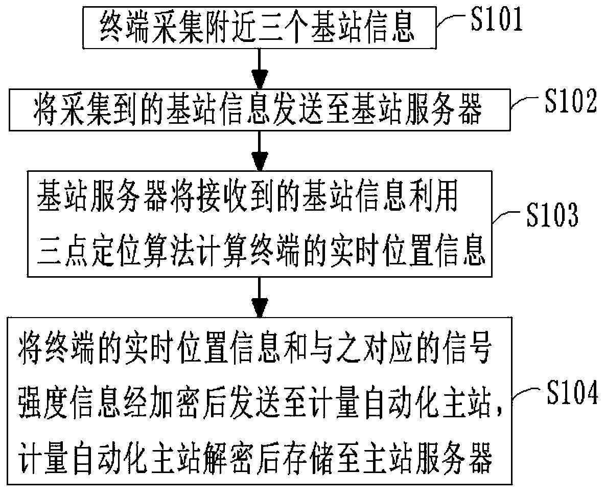
[0060] The present invention provides a terminal real-time location positioning method, figure 1 It is the flow chart of its embodiment one, as figure 1 As shown, the terminal real-time position positioning method: including:

[0061] S101. The terminal collects information about three nearby base stations, where the base station informat...


PUM


Abstract

The invention provides a terminal real-time position positioning method, a terminal real-time position positioning system, a terminal full-life-cycle monitoring method and a terminal full-life-cycle monitoring system. The terminal full-life-cycle monitoring method comprises the steps of: collecting initial position information of a terminal, and collecting current position information and signal intensity information of the terminal by adopting the terminal real-time position positioning method; training a classifier model according to the initial position information and the signal intensityinformation of the terminal to obtain a binary classifier model for judging whether the position of the terminal is abnormal or not; inputting the current position information and the signal intensityinformation of the to-be-tested terminal into the classifier model, and extracting a classification result by means of a softmax network; and sending an alarm prompt to related personnel when the position and the signal intensity of the terminal are abnormal. The terminal real-time position positioning method and the terminal full-life-cycle monitoring method can collect the real-time position information of the terminal timely and precisely, send out the alarm prompt when the position of the terminal is abnormal, and improve the daily maintenance working efficiency of the terminal.

Description

technical field [0001] The invention belongs to the technical field of metering automation terminals, and in particular relates to a terminal real-time location positioning method and system, and a terminal full life cycle monitoring method and system. Background technique [0002] As the State Grid and China Southern Power Grid vigorously build smart grids, the use of metering automation terminals is becoming more and more extensive. In terms of improving the automatic collection of power grid electricity, the metering automation terminal has played a huge role in promoting. At the same time, the huge number of metering automation terminals also puts forward higher requirements for management and maintenance. As the pace of urban construction gradually accelerates, the location of power supply equipment often migrates, and the traditional method of using manual or offline electronic marking can no longer meet the current rapid development needs. How to monitor terminal loca...

Claims


Application Information

Patent Timeline
Patent Type & Authority Applications(China)
IPC IPC(8): G01S11/06
CPCG01S11/06
Inventor 刘运兵尹志强曹梦娟裴俊艺林艳青成周赵渊李哲孙志吴进鸿李宜恒潘靖张华欣
Owner GUIZHOU POWER GRID CO LTD
Learn More