Working condition management system and method

A technology for managing systems and working conditions, applied in image data processing, electrical digital data processing, special data processing applications, etc., to achieve the effect of reducing information communication barriers

Pending Publication Date: 2020-05-08
DMS CORP
View PDF4 Cites 4 Cited by
  • Summary
  • Abstract
  • Description
  • Claims
  • Application Information

AI Technical Summary

Problems solved by technology

[0003] However, there are many production devices and equipment installed in the current factory. In the daily production and operation of the factory, especially for large factories, there are a lot of inspections and maintenance work every day to ensure the safety and stable operation of the factory. There are a lot of cross-operations in the factory, and there are many factory safety factors involved, and the job responsibilities for factory

Method used


Image

  • Working condition management system and method
  • Working condition management system and method
  • Working condition management system and method

Examples


Embodiment 1

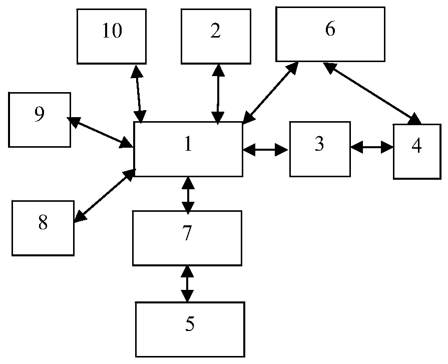
[0026] Such as figure 1As shown, the present invention provides a working condition management system, which at least includes a data modeling unit 1 , a working condition collecting unit 2 , a working condition analyzing unit 3 and a comprehensive management unit 4 . The data modeling unit 1 is used to carry out three-dimensional virtual simulation of the production elements in the factory, and then realize the digital transformation of the production elements from the physical state to the 3D virtual state to obtain a three-dimensional virtual factory. For example, the data modeling unit 1 can build a three-dimensional virtual simulation model of production factors by means of panoramic scanning. The working condition collection unit 2 is used to collect the production data involved in the production factors. Taking a factory as an example, the factors of production include at least all the buildings in the factory, the production equipment placed in the buildings, and the ...

Embodiment 2

[0045] This embodiment is a further improvement on Embodiment 1, and repeated content will not be repeated here.

[0046] Such as figure 1 As shown, the working condition management system also includes a communication interface 5 , a display unit and an interaction unit 7 . The communication interface 5 can perform two-way communication with other factory management systems, and then can acquire various production data, and transmit the collected production data to the working condition acquisition unit 2 . Other factory management systems include, but are not limited to, ERP systems, MES systems, E-HR systems, CPC systems, EAM systems, PLS systems, SRM systems, PLM systems, and QMS systems. For example, the communication interface 5 can communicate with the EAM system, and then can query the historical work order data of the factory and create and initiate the work order data. Or communicate with the equipment management system, and then you can query the spare parts data ...

Embodiment 3

[0048] This embodiment is a further improvement on the foregoing embodiments, and repeated content will not be repeated here.

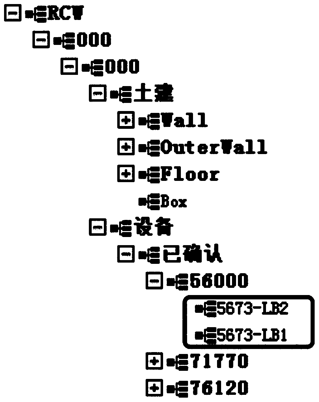
[0049] Preferably, in the physical physical environment of the factory, both the production elements and the environment elements can be configured with at least one of the first setting code, the second setting code and the third setting code that can be visually displayed. Specifically, several factories can be arranged in one park. For example, for car companies, different models are often configured in different factories for manufacturing. In the actual physical environment, in order to distinguish different factories, it is necessary to use factories with different names such as A factory, B factory, and C factory. distinguish. "A factory, B factory, C factory" and so on are natural languages ​​that people can directly understand their meanings. In the present invention, natural languages ​​such as factory A, factory B, and factory C can be co...


PUM


Abstract

The invention relates to a working condition management system, which at least comprises: a data modeling unit capable of performing virtual simulation on production elements and/or environmental elements to obtain a three-dimensional virtual factory; a working condition acquisition unit which is at least capable of acquiring production data related to the production elements and acquiring a plurality of corresponding data items in a timed and content-fixed mode according to input query conditions, wherein the data items corresponding to the query conditions can be cached to a database; a display unit which can be used for carrying out visualization processing on the three-dimensional virtual factory; a working condition analysis unit which is configured in such a way that: comparing and analyzing the data items acquired by the working condition acquisition unit with the object data in the three-dimensional virtual factory obtained by the data modeling unit to obtain an object corresponding to each data item in the three-dimensional virtual factory and a spatial position coordinate of the object, wherein the object and the spatial position coordinate of the object can be displayedthrough a display unit.

Description

technical field [0001] The invention belongs to the technical field of working condition management, and in particular relates to a working condition management system and method. Background technique [0002] With the increasing awareness of global industrial alarm management, the factory alarm management technology used to improve the safety protection ability of the factory itself has been greatly improved. At present, the solution commonly used by major factories on the market to manage factory conditions is to collect alarm event information in the factory through the DCS (Distributed Control System) system, and through manual identification. Identify and judge the alarm event information so that the plant operators can deal with the corresponding abnormal conditions. However, this solution requires factory operators to spend a lot of time and energy to find appropriate information from the alarm event information provided by the DCS system to judge the abnormal workin...

Claims


Application Information

Patent Timeline
IPC IPC(8): G06F16/9038G06F16/903G06F16/909G06F16/901G06T17/05
CPCG06F16/9038G06F16/90335G06F16/909G06F16/901G06T17/05
Inventor 陈劲松
Owner DMS CORP
Why Eureka
Try Eureka