
Space splicing system and space splicing method

A splicing system and space technology, applied in the field of imaging, can solve the problems of spatial dislocation, no solution, data time synchronization and spatial synchronization cannot be guaranteed, etc., and achieve the effect of good real-time performance and large field of view.

Pending Publication Date: 2020-05-08
HANGZHOU YIYUQIANXIANG TECH CO LTD
View PDF0 Cites 0 Cited by
  • Summary
  • Abstract
  • Description
  • Claims
  • Application Information

AI Technical Summary

Problems solved by technology

However, the image of a single binocular camera has limitations in the field of view, and there is no complete solution for combining depth information in a 360-degree space or a larger space.
However, the use of multiple units for simultaneous acquisition and splicing makes the acquisition range larger, but the time synchronization and space synchronization of the data cannot be guaranteed; at the same time point, the acquisition action is somewhat slow and some is fast; after the data is collected, it is integrated into the In a three-dimensional coordinate system, the space may be misaligned

Method used


Image

  • Space splicing system and space splicing method
  • Space splicing system and space splicing method
  • Space splicing system and space splicing method

Examples


Embodiment 1

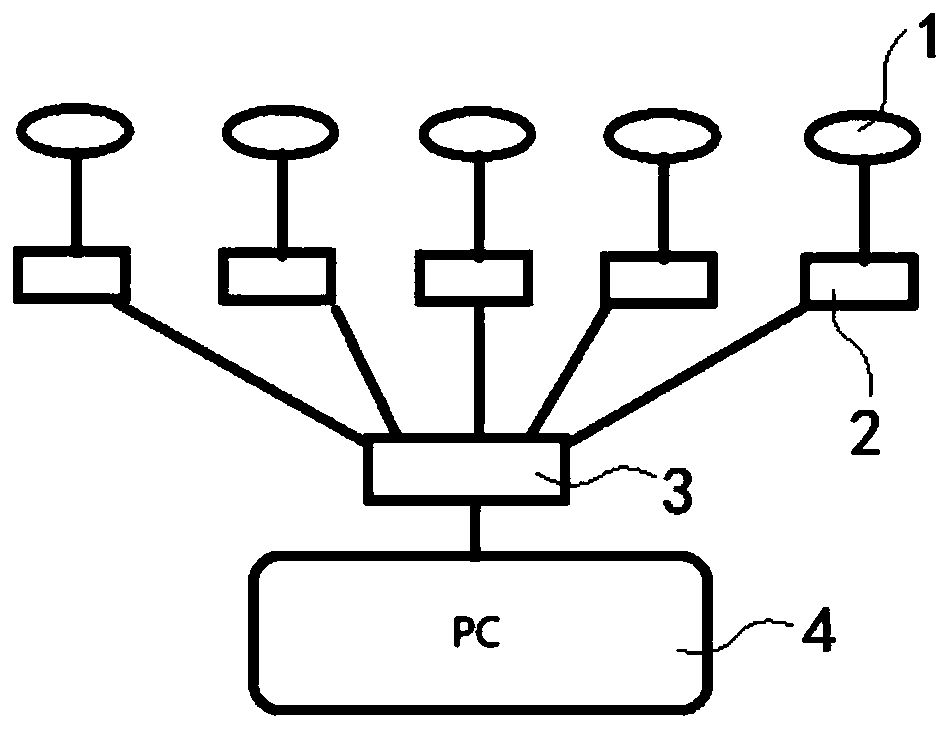
[0038] This embodiment provides a space splicing system, such as figure 1 , Including a camera, a plurality of said cameras are respectively located on a plurality of planes in a three-dimensional space, wherein a first camera is provided on a plane perpendicular to each plane on which a camera is provided, and the cameras of the cameras are Towards the outside of the three-dimensional space, the camera and the controller are connected. The data collected by each camera is transmitted to the controller, and the controller processes the data of each camera and the first camera to obtain the corresponding image information. Through the comprehensive coverage and cooperation of each camera and the first camera in angle and orientation, it is possible to achieve 360° image information collection without dead angles. Expand the visual range of image acquisition.

[0039] As a preferred embodiment of this embodiment, such as Figure 4 As shown, there are 4 cameras in total, and 1 fi...

Embodiment 2

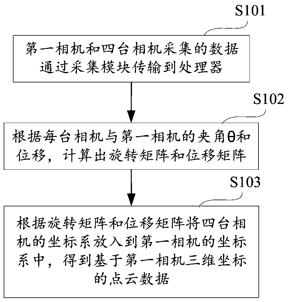
[0047] This embodiment also provides a spatial splicing method. The spatial splicing system according to the first embodiment includes: S101, a first camera and data collected by the camera are transmitted to a processor through an acquisition module; S102, according to The angle θ and displacement between each camera and the first camera are calculated, the rotation matrix and the displacement matrix are calculated, S103, the coordinate system of the camera is put into the coordinate system of the first camera according to the rotation matrix and the displacement matrix, and the The point cloud data of the three-dimensional coordinates of the first camera.

[0048] Putting the coordinate system of the camera into the coordinate system of the first camera according to the rotation matrix and the displacement matrix is ​​further as follows: firstly, the coordinate points x, y, and z of the data collected by the camera are sequentially rotated around the X axis, Rotation of Y axis ...


PUM


Abstract

The invention discloses a space splicing system and a space splicing method, and belongs to the technical field of imaging. The system comprises a plurality of cameras, and the plurality of cameras are respectively located on a plurality of planes in a three-dimensional space, wherein a first camera is arranged on one plane perpendicular to each plane provided with one camera, the camera heads ofthe cameras face the outside of the three-dimensional space, and the cameras are connected with a controller. The method comprises the following steps: data acquired by the first camera and the cameras are transmitted to a processor through an acquisition module; and calculating a rotation matrix and a displacement matrix according to the included angle theta and the displacement between each camera and the first camera, and putting the coordinate system of the cameras into the coordinate system of the first camera according to the rotation matrix and the displacement matrix to obtain point cloud data based on the three-dimensional coordinate of the first camera. Aiming at the technical problems of data synchronism and space synchronism of a plurality of binocular cameras in the prior art,the data synchronism and the space synchronism can be ensured.

Description

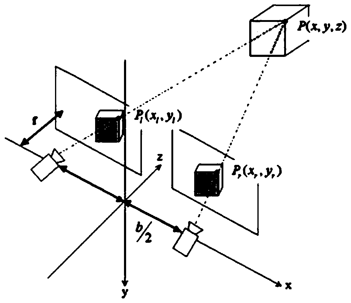
Technical field [0001] The present invention relates to the field of imaging technology, in particular to a spatial splicing system and method. Background technique [0002] The working principle of the binocular camera is to use the two cameras on this camera to shoot at the same time, compare the two images obtained, will get the different coordinate points of the same object in the two images, and use the mathematical model to calculate the actual object to The distance of the camera, such as figure 2 Shown. However, the image of a single binocular camera has the limitation of the field of view, and there is no complete solution for combining the depth information in a 360-degree space or a larger space. However, the use of multiple units for simultaneous acquisition and splicing makes the acquisition range larger, but the time synchronization and spatial synchronization of the data cannot be guaranteed; the acquisition actions at the same time point are somewhat slower and s...

Claims


Application Information

Patent Timeline
Patent Type & Authority Applications(China)
IPC IPC(8): G06T3/40G06T3/60
CPCG06T3/4038G06T3/60G06T2200/32G06T2207/10012
Inventor 沈诚
Owner HANGZHOU YIYUQIANXIANG TECH CO LTD
Learn More