
Quantum network coding method based on quantum state non-loss

A network coding, quantum state technology used in key distribution

Active Publication Date: 2020-05-08
南京万般上品信息技术有限公司
View PDF7 Cites 2 Cited by
  • Summary
  • Abstract
  • Description
  • Claims
  • Application Information

AI Technical Summary

Problems solved by technology

[0004] In 2010, Ma et al. proposed probabilistic quantum network coding on butterfly networks. This scheme achieves perfect quantum state transmission by pre-sharing non-maximal entangled states between senders. However, due to the use of non-maximal Entangled states make transmission success probabilistic

Method used


Image

  • Quantum network coding method based on quantum state non-loss
  • Quantum network coding method based on quantum state non-loss
  • Quantum network coding method based on quantum state non-loss

Examples


Embodiment approach 1

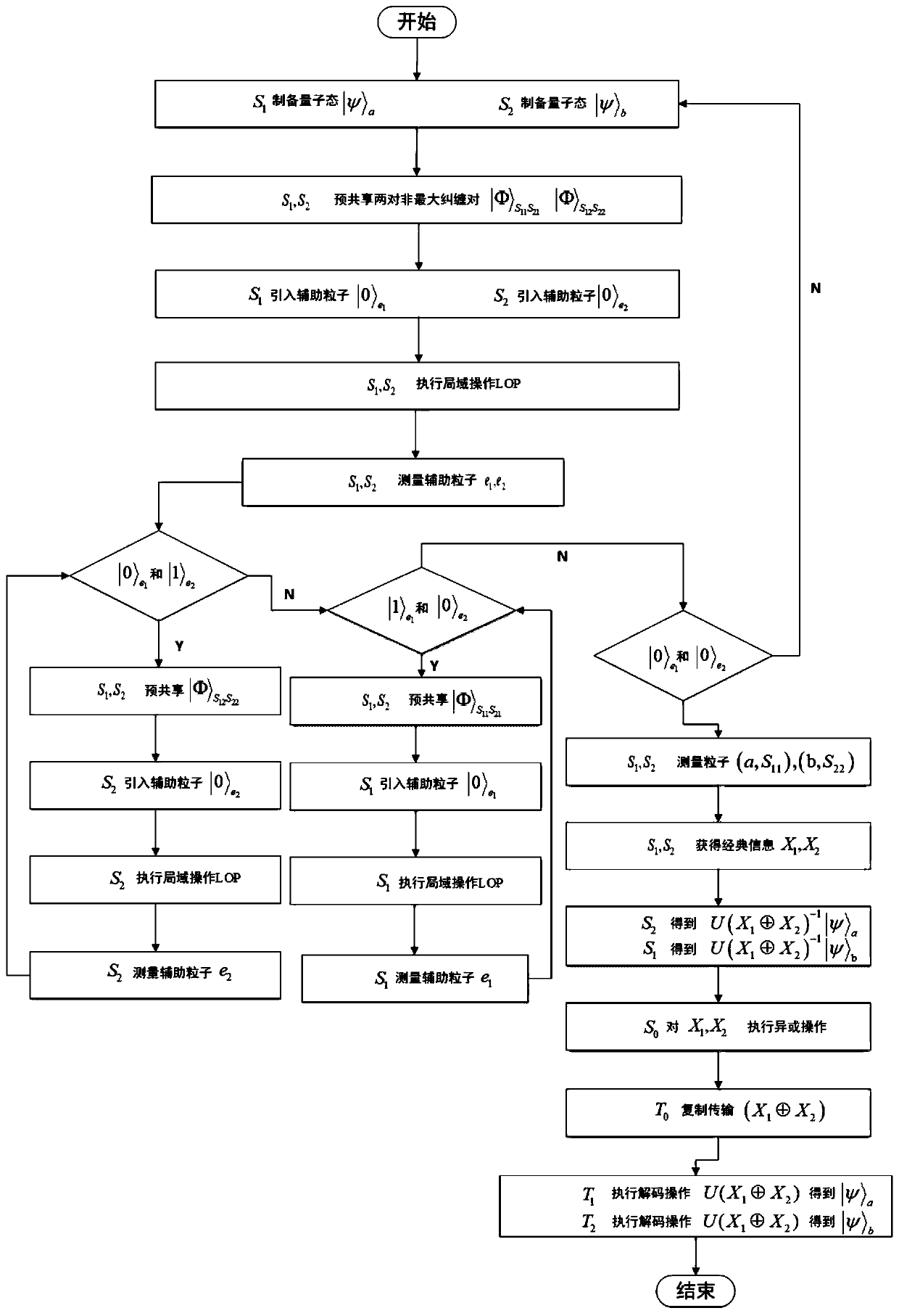
[0033] Embodiment 1 A quantum 2-pair network coding technology based on quantum state not being lost

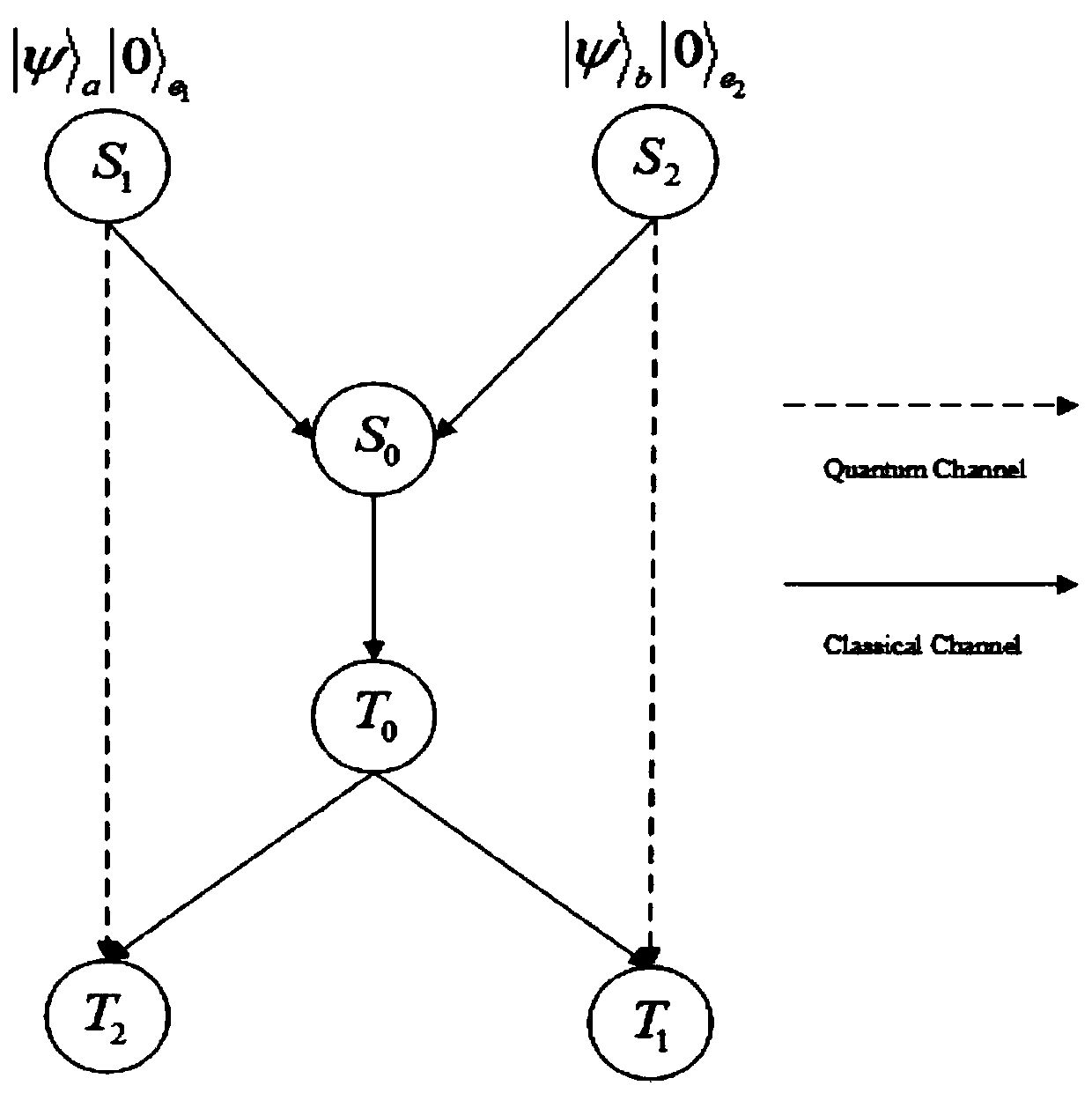
[0034] Step 1: If figure 1 As shown, it is assumed that each sender can prepare two particles in a non-maximally entangled state, and then send one particle in the entangled state to another sender.

[0035] In a butterfly network, two pairs of non-maximally entangled states are pre-shared between two senders, namely and Sender S 1 The quantum state to be sent is |ψ> a , the sender S 2 The quantum state to be sent is |ψ> b .

[0036] In order to realize the quantum network coding scheme without information loss, it is necessary to add an auxiliary particle locally at each sender, the initial state is |0>, and the initial state of the total system is:

[0037]

[0038] Among them, the sender S 1 Possess Particle S 11 , S 12 , the auxiliary particle e 1 , and the quantum state to be transmitted |ψ> a .

[0039] Sender S 2 Possess Particle S 21 , S 22 , the...

Embodiment approach 2

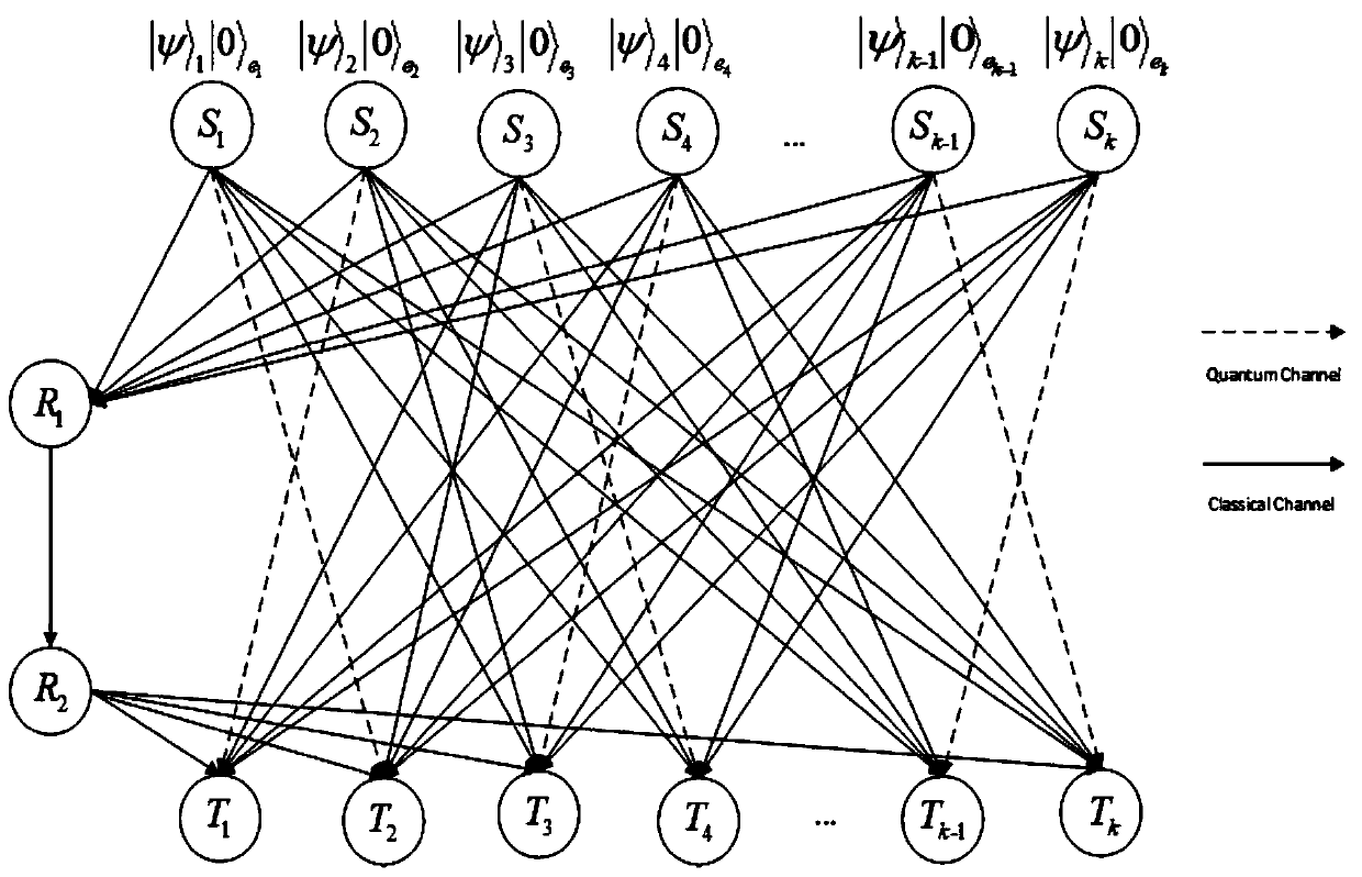
[0069] Embodiment 2 A quantum 3-pair network coding technology based on quantum state not being lost

[0070] Step 1: If Figure 4 As shown, in a 3-pair network, we specify S i to R 1 The lines between are classic channels. R 1 to R 2 The connection of is the classical channel; R 2 to T i The connection between is the classic channel; S 1 to T 2 is the quantum channel; S 1 to T 3 is the classic channel; S 2 to T 1 is the quantum channel; S 2 to T 3 is the quantum channel; S 3 to T 1 is the classic channel; S 3 to T 2 for the classic channel.

[0071] Both the quantum channel and the classical channel are only allowed to be used once for each information transmission, and the capacity of the quantum channel is 1 qubit, and the capacity of the classical channel is 1 bit.

[0072] First, the sender S 1 with S 2 share two pairs of non-maximally entangled states and Sender S 2 with S 3 share a pair of non-maximally entangled states

[0073] After each ...


PUM


Abstract

The invention discloses a quantum network coding method based on quantum state non-loss, and belongs to the technical field of network communication. The method is characterized in that two pairs of non-maximum entangled states are pre-shared between senders of the butterfly network, and perfect transmission of quantum states with fidelity of 1 can be realized by performing some local operations on the senders. By adding auxiliary particles to the sender, whether the quantum state is successful or not can be known before the quantum state is transmitted on the quantum network. The quantum state is not lost, that is, when transmission fails, the quantum state to be transmitted by the sender does not collapse to other states, and the quantum state is reproduced at the sender. When the measurement result of the auxiliary particles is | 0 >, | psi > a-| psi > b is realized; and when the measurement result of the auxiliary particles is | 1 >, | psi > a-| psi > a is realized. According to the quantum network coding based on quantum multi-unicast, perfect quantum state cross transmission is realized in a butterfly network model, a solution is provided for quantum 2-pair and k-pair networkcommunication problems, and the quantum network coding based on quantum multi-unicast has certain practical value.

Description

technical field [0001] The invention relates to a quantum network coding method based on the non-lost quantum state. By adding auxiliary resources and implementing local operations on the network sender, the perfect cross-transmission of the quantum state on the butterfly network can be realized, thereby improving the transmission efficiency of the quantum state , belonging to the field of network communication technology. Background technique [0002] Improving the efficiency of information transmission in the network is an important research topic in the field of information science. In 2000, based on the butterfly network, Ahlswede and others pointed out that through network coding, the maximum flow boundary of multicast routing transmission can be achieved, and the efficiency of information transmission can be improved, thus establishing the important position of network coding in the field of modern network communication research. . [0003] Researchers have applied t...

Claims


Application Information

Patent Timeline
IPC IPC(8): H04L9/08
CPCH04L9/0852H04L9/0858
Inventor 陈秀波徐刚潘兴博
Owner 南京万般上品信息技术有限公司
Learn More