Signal transmission method and device

A technology for signal transmission and terminal equipment, which is applied in the field of communication and can solve problems such as UE power consumption

Active Publication Date: 2020-05-08
VIVO MOBILE COMM CO LTD
View PDF4 Cites 9 Cited by
  • Summary
  • Abstract
  • Description
  • Claims
  • Application Information

AI Technical Summary

Problems solved by technology

[0004] Embodiments of the present invention provide a signal transmission method and device to so

Method used


Image

  • Signal transmission method and device
  • Signal transmission method and device
  • Signal transmission method and device

Examples


no. 1 example

[0060] Combine below figure 2 The shown flow chart of the signal transmission method illustrates the signal transmission method in the embodiment of the present invention, figure 2 It is a schematic flow chart of a signal transmission method provided by the embodiment of the present invention. For the network device side, the signal transmission method provided by the embodiment of the present invention includes steps 201 and 202:

[0061] Step 201: The network device sends first information.

[0062] Step 202: The network device sends M wake-up signals.

[0063] It should be noted that the above-mentioned step 201 and step 202 are only for distinguishing the steps, and the order of the steps is not limited. In the specific implementation, step 201 can be executed first and then step 202 can be executed, or the above-mentioned step 201 can be executed at the same time. and step 202, which is not limited in this embodiment of the present invention.

[0064] In the embodime...

no. 2 example

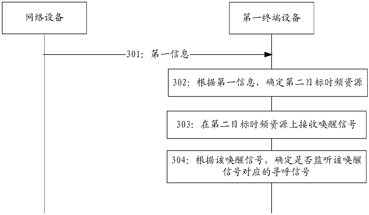
[0120] Combine below image 3 The shown flow chart of the signal transmission method illustrates the signal transmission method in the embodiment of the present invention, image 3 It is a schematic flowchart of a signal transmission method provided by the embodiment of the present invention. For the terminal device side, the signal transmission method provided by the embodiment of the present invention includes steps 301 to 304:

[0121] Step 301: The first terminal device receives first information from the network device.

[0122] Step 302: The first terminal device determines a second target time-frequency resource according to the first information.

[0123] Step 303: The first terminal device receives a wake-up signal on the second target time-frequency resource.

[0124] Step 304: The first terminal device determines whether to monitor the paging signal corresponding to the wake-up signal according to the wake-up signal.

[0125] In the embodiment of the present inve...

no. 3 example

[0162] Figure 4 A schematic structural diagram of a network device provided for implementing an embodiment of the present invention, such as Figure 4As shown, the network device 400 includes a sending module 401, wherein:

[0163] A sending module 401, configured to send first information.

[0164] The above-mentioned sending module 401 is also configured to send M wake-up signals.

[0165] Wherein, the above-mentioned first information is used to indicate the number N; the above-mentioned number N is the group number of the terminal equipment group obtained after grouping the X terminal equipment; the paging opportunities of the above-mentioned X terminal equipment are the same; the above-mentioned M wake-up signals are used to indicate Whether the terminal equipment of the N terminal equipment groups monitors the paging signal at the paging opportunity; a wake-up signal is used to indicate whether all or part of the terminal equipment of the N terminal equipment groups m...


PUM


Abstract

Embodiments of the present invention provide a signal transmission method and device, which are applied to the technical field of communications, so as to solve the problem of UE power consumption inthe existing wake-up signal transmission process. The method comprises the following steps: sending first information, and sending M wake-up signals, wherein the first information is used for indicating the number N, the number N is the number of terminal device groups obtained by grouping X terminal devices, paging opportunities of the X terminal devices are the same, the M wake-up signals are used for indicating whether the terminal devices of the N terminal device groups monitor paging signals at the paging opportunity, one wake-up signal is used for indicating whether the terminal devicesof all or part of the N terminal device groups monitor the paging signal at the paging opportunity, the group number of all or part of the terminal device groups is smaller than or equal to a first threshold, the first threshold is a positive integer, X and N are integers greater than 1, and M is a positive integer.

Description

technical field [0001] Embodiments of the present invention relate to the field of communication technologies, and in particular, to a signal transmission method and device. Background technique [0002] At present, in each Discontinuous Reception (DRX) cycle of the RRC (Radio Resource Control, Radio Resource Control) idle (idle) state, the user equipment (user equipment, UE) blindly detects the paging occasion (Paging Occasion , PO) before the paging (Paging) signal, the base station will transmit a wake-up signal to the UE, and the UE wakes up at a corresponding time to detect the wake-up signal. Wherein, if the wake-up signal instructs the UE to blindly detect the Paging Physical Downlink Control Channel (Paging Physical Downlink Control Channel, Paging PDCCH), the UE continues to blindly detect the subsequent corresponding Paging PDCCH; otherwise, the UE does not blindly detect the Paging PDCCH. [0003] However, in related technologies, a PO supports the transmission o...

Claims


Application Information

Patent Timeline
IPC IPC(8): H04W52/02H04W76/28
CPCH04W52/0229H04W76/28Y02D30/70
Inventor 姜大洁
Owner VIVO MOBILE COMM CO LTD
Why Eureka
Try Eureka