
Grain-oriented electrical steel sheet

An electromagnetic steel plate and directional technology, applied in the direction of circuits, magnetic objects, magnetic materials, etc., can solve the problems of increased cost, insufficient effect, and no synergistic effect

Active Publication Date: 2021-10-12
JFE STEEL CORP
View PDF23 Cites 0 Cited by
  • Summary
  • Abstract
  • Description
  • Claims
  • Application Information

AI Technical Summary

Problems solved by technology

However, the grain-oriented electrical steel sheet obtained by the conventional heat-resistant magnetic domain refinement method has the following problems: it is different from the grain-oriented electrical steel sheet obtained by the non-heat-resistant magnetic domain refinement method by laser or plasma flame irradiation. Insufficient iron loss reduction effect compared to
In this technology, there is no special synergistic effect on the combination of linear grooves and surface mirroring, and it is just a parallel use of multiple iron loss improvement methods.
In addition, the mirror surface treatment of the base iron interface brings about a significant increase in cost, which has become a problem

Method used


Image

  • Grain-oriented electrical steel sheet
  • Grain-oriented electrical steel sheet
  • Grain-oriented electrical steel sheet

Examples


Embodiment 1

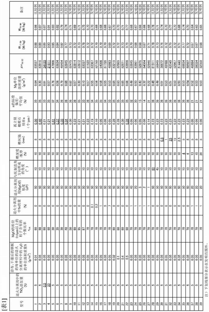
[0090] In terms of mass%, C: 0.06%, Si: 3.3%, Mn: 0.06%, P: 0.002%, S: 0.002%, Al: 0.025%, Se: 0.020%, Sb: 0.030%, Cu: 0.05% % and N: 0.0095% of the billet is loaded into a gas furnace, heated to 1230°C and held for 60 minutes, then heated at 1400°C for 30 minutes in an induction heating furnace, and hot-rolled to form a hot-rolled sheet with a thickness of 2.5mm. The hot-rolled sheet was annealed at 1000° C. for 1 minute, pickled, cold-rolled once to form a thickness of 1.7 mm, intermediate annealed at 1050° C. for 1 minute, pickled, and then used After secondary cold rolling to a final plate thickness of 0.23 mm, decarburization annealing was performed at 850° C. for 100 seconds in an oxidizing atmosphere mixed with hydrogen, nitrogen, and water vapor. Further adding TiO to MgO 2 An annealing separator and other reagents are mixed with water to form a slurry, which is coated on the surface of the steel sheet, dried, and then wound into a roll. At this time, use MgO with di...

Embodiment 2

[0098] A steel slab having the composition described in Table 2-1 and the remainder consisting of Fe and unavoidable impurities was produced by continuous casting, heated to a temperature of 1380°C, and then hot rolled to obtain a slab with a thickness of 2.0 mm. The hot-rolled sheet was annealed at 1030° C. for 10 seconds, then cold-rolled, and finished into a cold-rolled sheet with a final thickness of 0.20 mm. Thereafter, decarburization annealing is performed. Decarburization annealed at 50vol% H 2 -50vol%N 2 , Keep at 840°C for 100 seconds in a humid atmosphere with a dew point of 55°C. Next, the following three kinds of slurries (A), (B) and (C) were applied to each material, that is, (A) with the r of MgO 0.6 = 65%, MgO with a viscosity (after 30 minutes of stirring at 100 rpm) of 30 cP is the main component, and 10% of TiO is added 2 The annealed separator slurry, or (B) the r of MgO 0.6 = 65%, MgO with a viscosity of 50cP (after stirring with 100rpm impeller for ...


PUM

PropertyMeasurementUnit
thicknessaaaaaaaaaa

Abstract

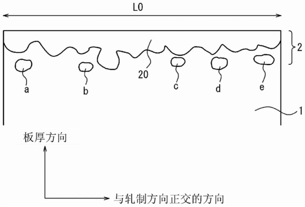
According to the present invention, for a grain-oriented electrical steel sheet having a coating mainly composed of predetermined forsterite on the surface and back of the steel sheet and having a plurality of grooves on the surface of the steel sheet, the average depth of the grooves is the thickness of the steel sheet The relative permeability μr when the frequency is 50Hz and the maximum magnetic flux density is 1.5T is AC magnetized. 15 / 50 It is 35000 or more, and the existence frequency of the part of the film that is separated from the continuous part and isolated in the interface of the above-mentioned steel plate and the above-mentioned film in the cross-section perpendicular to the rolling direction of the above-mentioned steel plate is set to 0.3 pieces / μm or less, and it can be realized. Further reduction of iron loss in grain-oriented electrical steel sheets.

Description

technical field [0001] The present invention relates to a grain-oriented electrical steel sheet mainly used as an iron core of a transformer, and in particular to a grain-oriented electrical steel sheet subjected to heat-resistant magnetic domain refinement without impairing the effect of reducing iron loss even if it is subjected to stress relief annealing. Background technique [0002] As a method of reducing the magnetic domain width of a grain-oriented electrical steel sheet to improve iron loss, two methods of magnetic domain refinement described below are mainly mentioned. [0003] That is, although the iron loss is improved by providing the thermally strained region in a linear shape, a non-heat-resistant magnetic domain refinement method that loses the iron loss improvement margin (no heat resistance) by subsequent heating such as annealing, And a heat-resistant magnetic domain refinement method in which linear grooves of a predetermined depth are provided on the sur...

Claims


Application Information

Patent Timeline
Patent Type & Authority Patents(China)
IPC IPC(8): C21D8/12C22C38/00C23C22/00H01F1/147C22C38/60
CPCC21D8/12C22C38/00C22C38/60C23C22/00H01F1/147C21D8/1283C21D8/1244C21D6/005C21D6/008C21D8/1222C21D8/1233C21D8/1261C21D9/46C22C38/001C22C38/002C22C38/02C22C38/04C22C38/06C22C38/16H01F1/16
Inventor 千田邦浩渡边诚冈部诚司吉崎聪一郎
Owner JFE STEEL CORP
Learn More