Laser cleaning method and device

A laser cleaning and cleaning device technology, applied in the field of laser cleaning, can solve the problems of poor consistency of cleaning tanks, cleaning, etc., and achieve the effect of ensuring position consistency

Active Publication Date: 2021-08-31
GUANGDONG LYRIC ROBOT INTELLIGENT AUTOMATION CO LTD
View PDF0 Cites 0 Cited by
  • Summary
  • Abstract
  • Description
  • Claims
  • Application Information

AI Technical Summary

Problems solved by technology

In the prior art, although laser cleaning has been used to form a cleaning tank at the coating film of the base tape, it is impossible to guarantee that the position to be cleaned will be cleaned accurately every time, which leads to poor consistency of the positions where the cleaning tank is formed

Method used


Image

  • Laser cleaning method and device
  • Laser cleaning method and device
  • Laser cleaning method and device

Examples


Embodiment 1

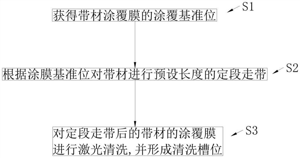
[0045] refer to figure 1 , figure 1 It is a flow chart of the laser cleaning method in Embodiment 1. The laser cleaning method in the present embodiment comprises the following steps:

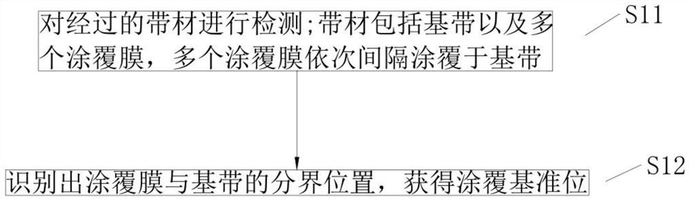
[0046] S1, obtaining the coating reference position of the strip coating film.

[0047] S2, carrying out fixed-section running of the strip with a preset length according to the coating reference position.

[0048] S3, laser cleaning is performed on the coating film of the strip after the fixed-segment running.

[0049] Before laser cleaning the coating film of the strip, the coating reference position will be detected first, and the strip will be positioned and moved with a preset length according to the coating reference position, so that the movement of the coating film is definite. Furthermore, the position to be cleaned of the coated film of the strip can be accurately determined, ensuring the consistency of the position where the cleaning tank is formed.

[0050] Preferably, in step ...

Embodiment 2

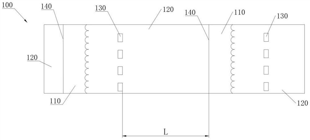
[0074] Continue to refer to image 3 and Figure 6 , Figure 6 It is a structural schematic diagram of the laser cleaning device in the second embodiment. The laser cleaning device in this embodiment includes a first cleaning device 1 . The first cleaning device 1 includes a first reference position detection mechanism 11 , a first laser cleaning mechanism 12 and a first main drive mechanism 13 arranged in sequence. The strip 100 passes through the first reference position detection mechanism 11 , the first laser cleaning mechanism 12 and the first main driving mechanism 13 in sequence. The first reference position detection mechanism 11 is used to obtain the coating reference position 140 of the coating film 120 of the strip 100, and the first main drive mechanism 13 carries out a predetermined length of the strip 100 according to the coating reference position 140. , so that the coating film 120 of the strip 100 after the fixed-section travel is placed in the cleaning po...

Embodiment 3

[0086] Continue to refer to image 3 , Figure 6 and Figure 8 , Figure 8 It is a schematic diagram of the direction of the strip in the second cleaning device in the third embodiment. The difference between the cleaning device in this embodiment and the second embodiment is that: the first reference position detection mechanism 11, the first laser cleaning mechanism 12 and the first main drive mechanism 13 cooperate to clean the coating film on the surface A of the strip. Laser cleaning is to continuously clean the coating film 120 on the A side of the strip 100 . The second cleaning device 2 also includes a surface-changing tape transport mechanism 24 . The surface-changing tape transport mechanism 24 is used to change the surface of the strip before laser cleaning, so that the second reference position detection mechanism 21, the surface-changing tape transport mechanism 24, the second laser cleaning mechanism 22 and the second main drive mechanism 23 are matched to ea...


PUM


Abstract

The invention discloses a laser cleaning method, which includes the following steps: obtaining the coating reference position of the coating film of the strip, carrying out a predetermined length of strip running on the strip according to the coating reference position, Laser cleaning is carried out on the coated film of the strip material; the invention also discloses a laser cleaning device. The invention of the present application detects the coating reference position before laser cleaning the coating film of the strip, and carries out positioning and running of the strip with a preset length according to the coating reference position, so that the movement of the coating film It is determined, so that the position to be cleaned of the coated film of the strip can be accurately determined, ensuring the consistency of the position where the cleaning tank is formed.

Description

technical field [0001] The present invention relates to the technical field of laser cleaning, in particular to a laser cleaning method and device. Background technique [0002] In the production process of the battery, it is necessary to remove the coating film in the set position area of ​​the anode pole piece by laser cleaning to form a cleaning tank, so that the base material in the cleaning tank is exposed and meets the requirements of tab welding. In the prior art, although laser cleaning has been used to form a cleaning tank at the coating film of the base tape, it is impossible to ensure that the position to be cleaned is accurately cleaned every time, which leads to poor consistency of the positions where the cleaning tank is formed. Contents of the invention [0003] Aiming at the deficiencies of the prior art, the present invention provides a laser cleaning method and device. [0004] A laser cleaning method disclosed in the present invention comprises the foll...

Claims


Application Information

Patent Timeline
Patent Type & Authority Patents(China)
IPC IPC(8): B08B7/00B08B13/00
CPCB08B7/0042B08B13/00
Inventor 周明浪蔡文杰钟小兰
Owner GUANGDONG LYRIC ROBOT INTELLIGENT AUTOMATION CO LTD
Why Eureka
Try Eureka