
A kind of forged steel soft seal floating ball valve

A floating ball valve and soft seal technology, applied in shaft seal, valve details, valve device, etc., can solve the problems of floating ball valve control flow rate changes, different rotation angles, and maintenance personnel are easy to touch the valve by mistake, so as to prevent accidental touch the effect of the situation

Active Publication Date: 2021-12-21
SHANGHAI YAAO VALVE CO LTD
View PDF11 Cites 0 Cited by
  • Summary
  • Abstract
  • Description
  • Claims
  • Application Information

AI Technical Summary

Problems solved by technology

[0004] When the above patents are used, in order to facilitate management and prevent unrelated personnel from arbitrarily adjusting the floating ball valve, the floating ball valves on the pipeline are often arranged in a control box. Since each floating ball valve is fixed with a hand valve, and the rotation of the hand valve The angles are often different (the flow rate requirements in different pipelines are different). During the maintenance process, maintenance personnel often touch the hand valve by mistake, which will cause changes in the flow rate controlled by the floating ball valve, and it is very difficult to restore the original state.

Method used


Image

  • A kind of forged steel soft seal floating ball valve
  • A kind of forged steel soft seal floating ball valve
  • A kind of forged steel soft seal floating ball valve

Examples


Embodiment 1

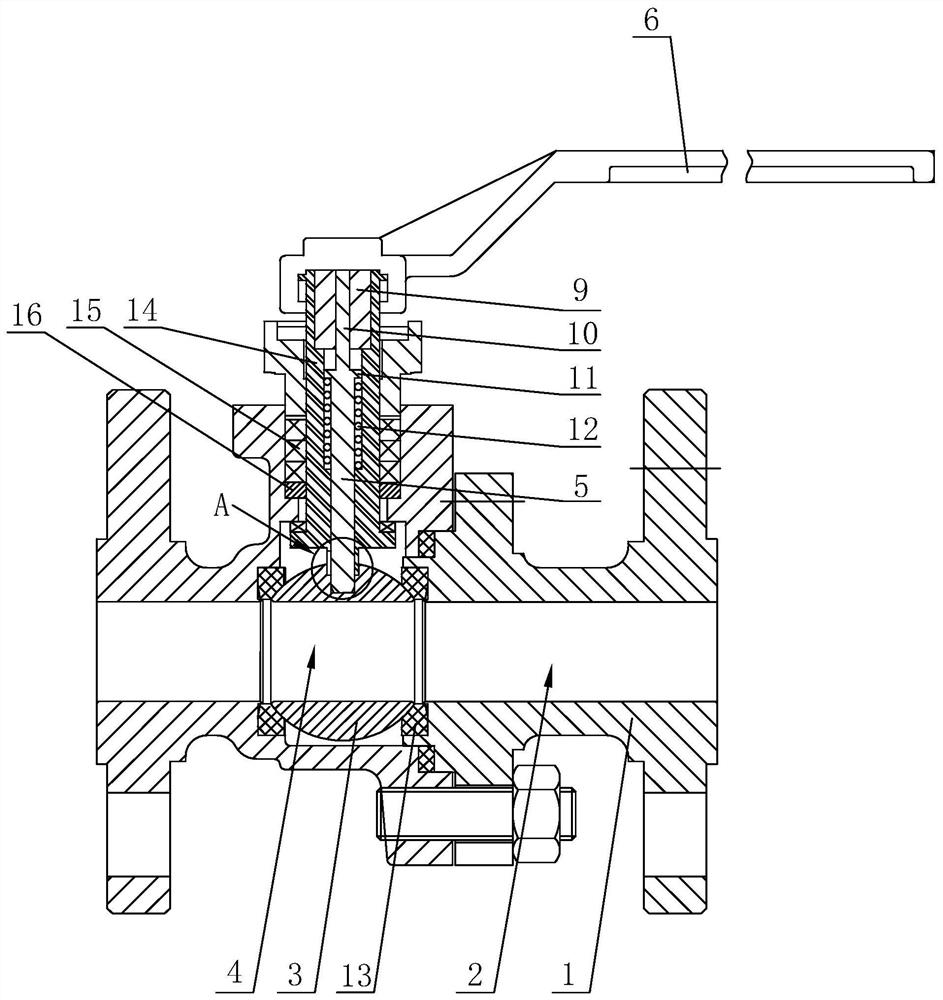
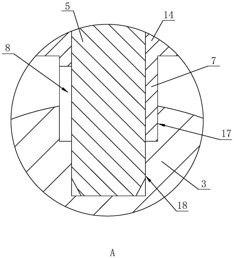
[0034] A forged steel soft seal floating ball valve, such as figure 1 and figure 2 As shown, the valve body 1 is included, and a flow channel 2 is opened through the valve body 1. The valve body 1 is rotatably connected with a valve ball 3 in the flow channel 2, and a valve hole 4 is opened on the valve ball 3. When in use, the flow channel 2. The internal fluid is liquid or gas. By rotating the valve ball 3, the valve hole 4 is misaligned with the flow channel 2, so as to realize the adjustment or cut-off of the flow. Both ends of the valve hole 4 on the valve ball 3 in the valve body 1 are fixed with sealing valve seats 13 , and the position limitation and sealing of the valve ball 3 are realized through the sealing valve seats 13 .

[0035] A rotating sleeve 14 is rotatably connected to one side of the valve body 1 and the valve ball 3, and a packing 15 and a packing pad 16 are also arranged between the rotating sleeve 14 and the valve body 1 to realize the smooth rotatio...

Embodiment 2

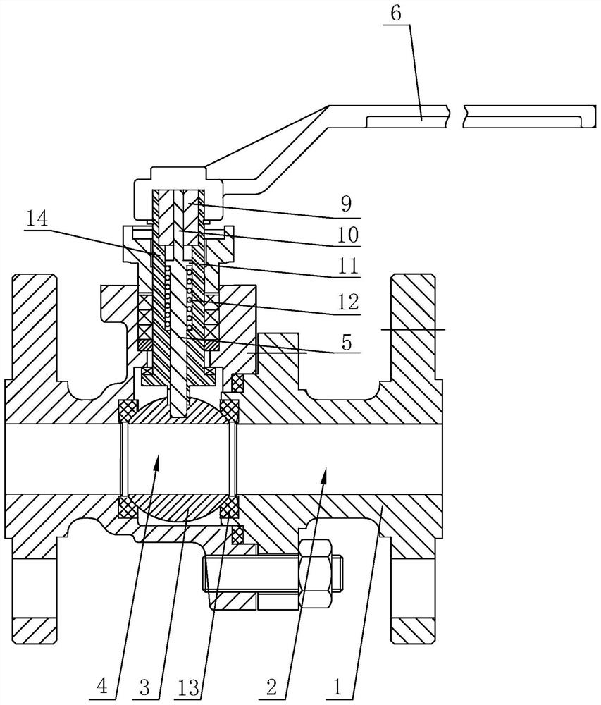
[0042] A forged steel soft seal floating ball valve, such as image 3 As shown, the difference from Embodiment 1 is that the end of the rotating sleeve 14 away from the valve ball 3 is set in a regular hexagonal shape, and one end of the valve handle 6 is plug-fitted with the end of the rotating sleeve 14 away from the valve ball 3 . A plurality of floating ball valves can be adjusted by using one valve handle 6, so as to avoid affecting maintenance operations due to the existence of the valve handle 6.


PUM


Abstract

The invention discloses a forged steel soft-sealed floating ball valve, which relates to the field of ball valves and comprises a valve body, in which a flow passage is opened through the valve body, and a valve ball is rotatably connected to the valve body in the flow passage, and a valve hole is opened through the valve ball; The valve body is also rotatably connected with a rotating sleeve, which is elastically and telescopically provided with a transmission rod for plugging and driving with the valve ball. Stem handle. Aiming at the problem in the prior art that it is easy to accidentally touch the hand valve to cause the flow limit of the floating ball valve to change, the present invention sets the transmission rod elastically. Only when the transmission rod is pressed down, the transmission rod is connected with the valve ball in transmission, and the flow rate is adjusted. The transmission rod shrinks to the valve ball. In the body, the rotation of the rotating sleeve cannot drive the valve ball to rotate, which effectively avoids the occurrence of accidental contact.

Description

technical field [0001] The invention relates to the field of ball valves, in particular to a forged steel soft-sealed floating ball valve. Background technique [0002] The ball of the ball valve is floating. Under the action of medium pressure, the ball can produce a certain displacement and press tightly on the sealing surface of the outlet end to ensure the seal of the outlet end. The floating ball valve has a simple structure and good sealing performance. [0003] For the existing floating ball valve structure, such as the Chinese patent with the patent publication number CN206874866U, it discloses a floating ball valve with a locking device, including a floating ball valve body, a locking disc is installed on the top of the floating ball valve body, and the locking disc A top nut is installed above the top nut, a hand valve is set above the top nut, a valve stem is embedded on the locking plate, packing is set on both sides of the valve stem, and a floating ball spool ...

Claims


Application Information

Patent Timeline
Patent Type & Authority Patents(China)
IPC IPC(8): F16K5/06F16K5/08F16K31/60F16K35/16F16K41/02
CPCF16K5/0647F16K5/0694F16K5/0673F16K5/0626F16K31/602F16K35/16
Inventor 刘丽艳杨剑忠杨鑫城杨欣梦兰勇军占凯丰
Owner SHANGHAI YAAO VALVE CO LTD
Learn More