Fresh air device with reasonable space layout

A technology for fresh air installation and space, applied in the directions of space heating and ventilation, space heating and ventilation details, ventilation systems, etc., can solve problems such as affecting the user experience, increasing the difficulty of assembly, and increasing processing costs, so as to increase the fresh air blowing area. area, improve the compactness of the layout, and reduce the size of the housing

Pending Publication Date: 2020-05-15
ZHEJIANG YOUBANG INTEGRATED CEILING
View PDF0 Cites 0 Cited by
  • Summary
  • Abstract
  • Description
  • Claims
  • Application Information

AI Technical Summary

Problems solved by technology

[0002] The existing fresh air device includes a housing and a fan arranged in the housing, an air inlet assembly and an air outlet assembly. The air outlet assembly includes an air outlet opening arranged on the housing. The axis is set corresponding to the axis of the air outlet opening, thereby improving the air flow efficiency by reducing the airflow resistance, but this structure requires a special installation space for the air inlet component in the housing, resulting in an excessively large housing volume, which increases the processing cost , it also puts forward higher requirements on the space size for installing the fresh air device, and needs to configure a larger-sized decorative panel, which increases the difficulty of assembly
[0003] In addition, the fresh air device includes a fresh air path and a circulating air path. Since there is a filter in the fresh air path, the wind resistance in the fresh air path is greater than the wind resistance in the circulating air path, and the flow rate of the fresh air device will change when the airflow source changes. , resulting in uneven air flow from the fresh air device, affecting user experience

Method used


Image

  • Fresh air device with reasonable space layout
  • Fresh air device with reasonable space layout
  • Fresh air device with reasonable space layout

Examples


Embodiment Construction

[0024] The substantive features of the present invention will be further described below in conjunction with the accompanying drawings and specific embodiments.

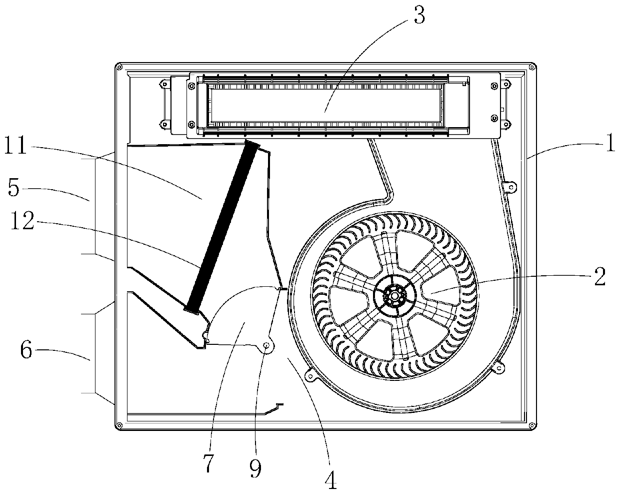
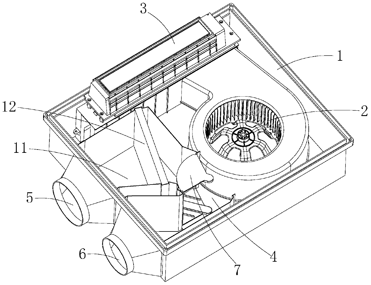
[0025] like figure 1 A fresh air device with a reasonable spatial layout is shown, which is composed of a housing 1 and an air duct arranged in the housing 1. The air duct includes a fan 2, an air inlet component connected to the air inlet of the fan 2, and an air inlet connected to the fan 2. 2 an air outlet assembly connected to the air outlet, the air outlet assembly includes an air outlet opening 3 connected to the fan 2, and the fan 2 and the air inlet assembly are respectively arranged at both ends of the side area of ​​the air outlet opening 3 , by offsetting the fan 2 to form an assembly space for accommodating the air intake assembly. Arranging the air inlet assembly and the fan 2 at both ends of the side of the air outlet assembly can not only effectively increase the fresh air blowing area of ​​the fresh ...


PUM


Abstract

The invention relates to a fresh air device with reasonable space layout. As an existing fresh air device has unreasonable layout, a shell is large in size, and the assembly of the existing fresh airdevice is troublesome. The fresh air device with the reasonable space layout comprises the shell, and an air passage arranged in the shell, wherein the air passage comprises a draught fan, an air inlet component connected to an air inlet of the draught fan, and an air outlet component connected to an air outlet of the draught fan; the air outlet component comprises an air-out opening connected tothe draught fan; the draught fan and the air inlet component are respectively arranged at the two ends of the lateral part region of the air-out opening; and the assembly space for containing the airinlet component is formed by offsetting the draught fan. The air inlet component and the draught fan are arranged at the two ends of the lateral part of the air outlet component, so that the area of the fresh air blowing region of the fresh air device can be effectively increased by increasing the size of the air-out opening, and the installation space can also be provided for the air inlet component by offsetting the draught fan. The compactness of the layout is improved by reasonably using the side part space of the air outlet component, and further the assembly of the fresh air device is facilitated by reducing the size of the shell.

Description

technical field [0001] The invention relates to the field of household appliances, in particular to a fresh air device. Background technique [0002] The existing fresh air device includes a housing and a fan arranged in the housing, an air inlet assembly and an air outlet assembly. The air outlet assembly includes an air outlet opening arranged on the housing. The axis is set corresponding to the axis of the air outlet opening, thereby improving the air flow efficiency by reducing the airflow resistance, but this structure requires a special installation space for the air inlet component in the housing, resulting in an excessively large housing volume, which increases the processing cost , It also puts forward higher requirements on the space size for installing the fresh air device, and needs to configure a larger-sized decorative panel, which increases the difficulty of assembly. [0003] In addition, the fresh air device includes a fresh air path and a circulating air p...

Claims


Application Information

Patent Timeline
Patent Type & Authority Applications(China)
IPC IPC(8): F24F7/06F24F13/28F24F11/79F24F11/89
CPCF24F7/06F24F11/79F24F11/89F24F13/28
Inventor 时沈祥翁叶帆葛佳峰陈玉龙林圣全
Owner ZHEJIANG YOUBANG INTEGRATED CEILING
Why Eureka
Try Eureka