Camera shooting optical lens

A technology of optical lens and optical total length, which is applied in the field of optical lens, can solve the problems of irrational setting of focal power, lens distance and lens shape, inability to meet large aperture, ultra-thin, wide-angle, etc., and achieve good optical performance Effect

Active Publication Date: 2020-05-15
AAC OPTICS (CHANGZHOU) CO LTD
View PDF5 Cites 8 Cited by
  • Summary
  • Abstract
  • Description
  • Claims
  • Application Information

AI Technical Summary

Problems solved by technology

However, with the development of technology and the increase of diversified needs of users, as the pixel area of ​​the photosensitive device continues to shrink, and the system’s requirements for imaging quality continue to increase, the seven-element lens structure gradually appears in the lens design. Common Although the seven-element lens already has good optical performance, its focal power, lens spacing and lens shape settings still have certain irrationality, resulting in a lens structure that cannot meet the requirements of large aperture, large aperture, and lens shape while having good optical performance. Ultra-thin, wide-angle design requirements

Method used


Image

  • Camera shooting optical lens
  • Camera shooting optical lens
  • Camera shooting optical lens

Examples


no. 1 approach

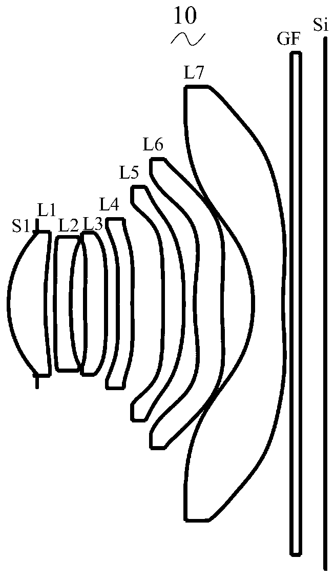
[0036] Referring to the accompanying drawings, the present invention provides an imaging optical lens 10 . figure 1 Shown is an imaging optical lens 10 according to a first embodiment of the present invention, and the imaging optical lens 10 includes seven lenses. Specifically, the imaging optical lens 10 sequentially includes, from the object side to the image side, an aperture S1, a first lens L1 with positive refractive power, a second lens L2 with negative refractive power, and a third lens with positive refractive power Lens L3, fourth lens L4 with negative refractive power, fifth lens L5 with positive refractive power, sixth lens L6 with positive refractive power, and seventh lens L7 with negative refractive power. Optical elements such as an optical filter GF may be provided between the seventh lens L7 and the image plane Si.

[0037] The first lens L1 is made of plastic material, the second lens L2 is made of plastic material, the third lens L3 is made of plastic mate...

no. 2 approach

[0154] The second embodiment is basically the same as the first embodiment, the meanings of symbols are the same as those of the first embodiment, and only the differences are listed below.

[0155] Table 5 and Table 6 show design data of the imaging optical lens 20 according to the second embodiment of the present invention.

[0156] 【table 5】

[0157]

[0158]

[0159] Table 6 shows aspherical surface data of each lens in the imaging optical lens 20 according to the second embodiment of the present invention.

[0160] 【Table 6】

[0161]

[0162] Table 7 and Table 8 show the design data of the inflection point and the stagnation point of each lens in the imaging optical lens 20 according to the second embodiment of the present invention.

[0163] 【Table 7】

[0164]

[0165]

[0166] 【Table 8】

[0167] Stationary number Stationary position 1 P1R1 0 P1R2 1 1.605 P2R1 0 P2R2 0 P3R1 1 0.625 P3R2 0 ...

no. 3 approach

[0172] The third embodiment is basically the same as the first embodiment, the meanings of symbols are the same as those of the first embodiment, and only the differences are listed below.

[0173] The fourth lens L4 has a positive refractive power, and the image side surface of the third lens L3 is concave at the paraxial position.

[0174] Table 9 and Table 10 show design data of the imaging optical lens 30 according to the third embodiment of the present invention.

[0175] 【Table 9】

[0176]

[0177] Table 10 shows aspherical surface data of each lens in the imaging optical lens 30 according to the third embodiment of the present invention.

[0178] 【Table 10】

[0179]

[0180]

[0181] Table 11 and Table 12 show the inflection point and stagnation point design data of each lens in the imaging optical lens 30 according to the third embodiment of the present invention.

[0182] 【Table 11】

[0183] Number of inflection points Inflection point posit...


PUM


Abstract

The invention relates to the field of optical lenses, and discloses a camera shooting optical lens. The camera shooting optical lens sequentially comprises a first lens with positive refractive power,a second lens with negative refractive power, a third lens with positive refractive power, a fourth lens, a fifth lens with positive refractive power, a sixth lens with positive refractive power anda seventh lens with negative refractive power from an object side to an image side. The following relational expressions are satisfied: 1.70<=f6/f<=5.00; -4.00<=R14/R13<=-1.00; -5.00<=f2/f<=-2.00; and1.00<=d8/d9<=2.00. The camera shooting optical lens has good optical performance such as large aperture, wide angle and ultra-thinness.

Description

technical field [0001] The invention relates to the field of optical lenses, in particular to an imaging optical lens suitable for portable terminal equipment such as smart phones and digital cameras, as well as imaging devices such as monitors and PC lenses. Background technique [0002] In recent years, with the rise of smart phones, the demand for miniaturized photographic lenses is increasing day by day, and the photosensitive devices of general photographic lenses are nothing more than Charge Coupled Device (CCD) or Complementary Metal Oxide Semiconductor (Complementary Metal Semiconductor) -Oxide Semiconductor Sensor, CMOS Sensor), and due to the improvement of semiconductor manufacturing process technology, the pixel size of the photosensitive device has been reduced, and the current electronic products have a trend of good functions and light, thin and short appearance. Therefore, with Miniaturized camera lenses with good imaging quality have become the mainstream in...

Claims


Application Information

Patent Timeline
Patent Type & Authority Applications(China)
IPC IPC(8): G02B13/00G02B13/06G02B13/18
CPCG02B13/0045G02B13/06G02B13/18G02B9/64
Inventor 杨永强
Owner AAC OPTICS (CHANGZHOU) CO LTD
Why Eureka
Try Eureka