LED matrix correction method based on Fourier laminated imaging

A technology of Fourier stacking and correction method, which is applied in the field of optical imaging and can solve problems such as image quality degradation

Active Publication Date: 2020-05-15
HANGZHOU DIANZI UNIV
View PDF9 Cites 7 Cited by
  • Summary
  • Abstract
  • Description
  • Claims
  • Application Information

AI Technical Summary

Problems solved by technology

[0005] Aiming at the problem that the final imaging quality is reduced due to the position deviation of the light source during lamination imaging, the present invention proposes an LED matrix correction method based on Fourier lamination imaging

Method used


Image

  • LED matrix correction method based on Fourier laminated imaging
  • LED matrix correction method based on Fourier laminated imaging
  • LED matrix correction method based on Fourier laminated imaging

Examples


Embodiment Construction

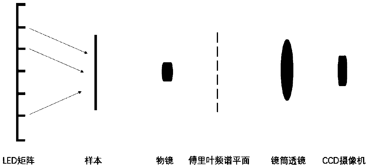
[0019] Step 1: To build the required hardware imaging system, a commonly used microscope is required, equipped with a low magnification objective lens (numerical aperture NA=0.08), and the sample to be resolved is placed on the stage; placed at a distance of h=7cm below the sample LED light source, using 15*15 LED elements to form a square lighting matrix, the distance between adjacent LED elements is d=5mm, and each LED element can emit a plane wave with a central wavelength λ=632nm; place a CCD camera at the imaging position above the system for Capture low-resolution images such as figure 1 shown.

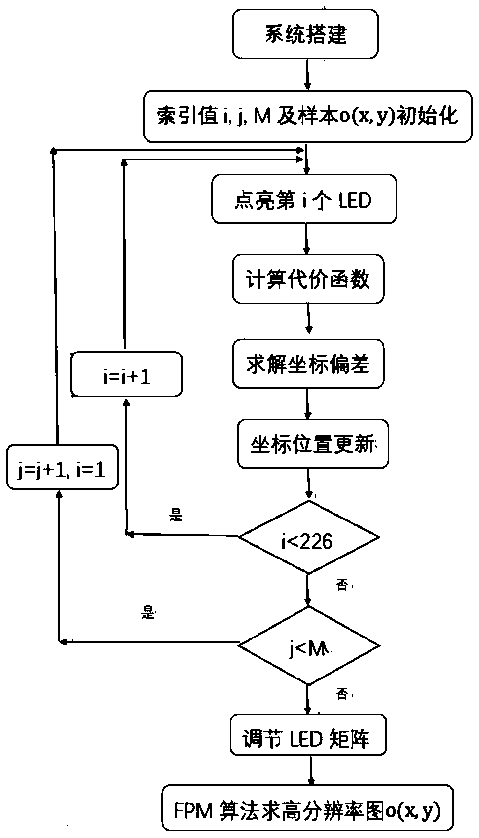
[0020] Step 2: Establish a coordinate system model for the system. Take the optical axis of the system as the z-axis, and the plane where the LED lighting matrix in the vertical optical axis direction is located is the XOY plane, where the central LED element is the center origin of the XOY plane (x 0 ,y 0 ). Then the coordinates of each LED element can be determined (x i ,...


PUM


Abstract

The invention relates to an LED matrix correction method based on Fourier laminated imaging. The method comprises the following steps: modeling an imaging system and an LED matrix, and defining an initial position vector of each LED; calculating a cost function according to the captured low-resolution image; correcting the position deviation of each LED by taking solving the global optimal solution of the cost function as a target; and reconstructing a high-resolution image of the target sample after correcting the position deviation of the LED illumination matrix according to a Fourier laminated imaging method. According to the invention, position correction of the illumination light source is completed according to the optical calculation imaging theory and data collected by the opticalimaging system. For a multi-light-source imaging system, if the position arrangement of the lighting elements is not reasonable, many adverse effects such as imaging quality reduction can be caused tothe imaging system; by correcting the positions of the light sources using the method of the invention, the imaging definition of the system can be well improved, and artifacts generated by the lightsource arrangement structure on images can be weakened.

Description

technical field [0001] The invention relates to the field of optical imaging, in particular to an LED matrix correction method based on Fourier stack imaging. Background technique [0002] Fourier stack imaging (FPM) is a new computational microscopic imaging method that has emerged in the field of optical imaging in recent years. High-resolution, wide-field imaging has the advantages of low cost, high resolution, and wide field of view. It has broad application prospects in medical imaging, biological sciences, and many other fields. [0003] In principle, the Fourier stack imaging technology uses the idea of ​​synthetic aperture. In the imaging process, instead of using a separate light source to illuminate the sample, a programmable LED lighting matrix is ​​placed under the sample (each LED element parameter are the same), turn on each LED in turn to scan the sample to obtain multiple low-resolution target intensity maps, and impose intensity constraints, process the col...

Claims


Application Information

Patent Timeline
Patent Type & Authority Applications(China)
IPC IPC(8): G02B21/06G02B21/36G06F17/16G06T3/40
CPCG02B21/06G02B21/365G06F17/16G06T3/4053
Inventor 颜成钢方运志姚婷婷孙垚棋张继勇张勇东
Owner HANGZHOU DIANZI UNIV
Why Eureka
Try Eureka