Computer waste heat utilization device and method

A computer and main box technology, applied in the computer field, can solve the problems of heat extraction, poor utilization, and inability to carry out more reasonable applications, and achieves the effect of not easy to fall off and easy to carry.

Inactive Publication Date: 2020-05-15
CHENGDU UNIV OF INFORMATION TECH
View PDF7 Cites 2 Cited by
  • Summary
  • Abstract
  • Description
  • Claims
  • Application Information

AI Technical Summary

Problems solved by technology

[0004] Therefore, the embodiment of the present invention provides a computer waste heat utilization device and utilization method. The present invention can regulate the utilization of waste heat according to seasonal changes. When the climate is cold, the waste heat can be utilized through the first waste heat utilization mechanism. When it is suitable or hot, the waste heat is utilized by the second waste heat utilization mechanism, which not only effectively utilizes the waste heat during use, but also facilitates the cooling treatment of the inside of the main chassis, prolonging the service life of the main chassis, so as to solve the problem of existing technology Due to the poor utilization of the waste heat generated by the computer, the internal heat can only be simply extracted, and the problem caused by a more reasonable application cannot be carried out.

Method used


Image

  • Computer waste heat utilization device and method
  • Computer waste heat utilization device and method
  • Computer waste heat utilization device and method

Examples


Embodiment Construction

[0030] The implementation mode of the present invention is illustrated by specific specific examples below, and those who are familiar with this technology can easily understand other advantages and effects of the present invention from the contents disclosed in this description. Obviously, the described embodiments are a part of the present invention. , but not all examples. Based on the embodiments of the present invention, all other embodiments obtained by persons of ordinary skill in the art without making creative efforts belong to the protection scope of the present invention.

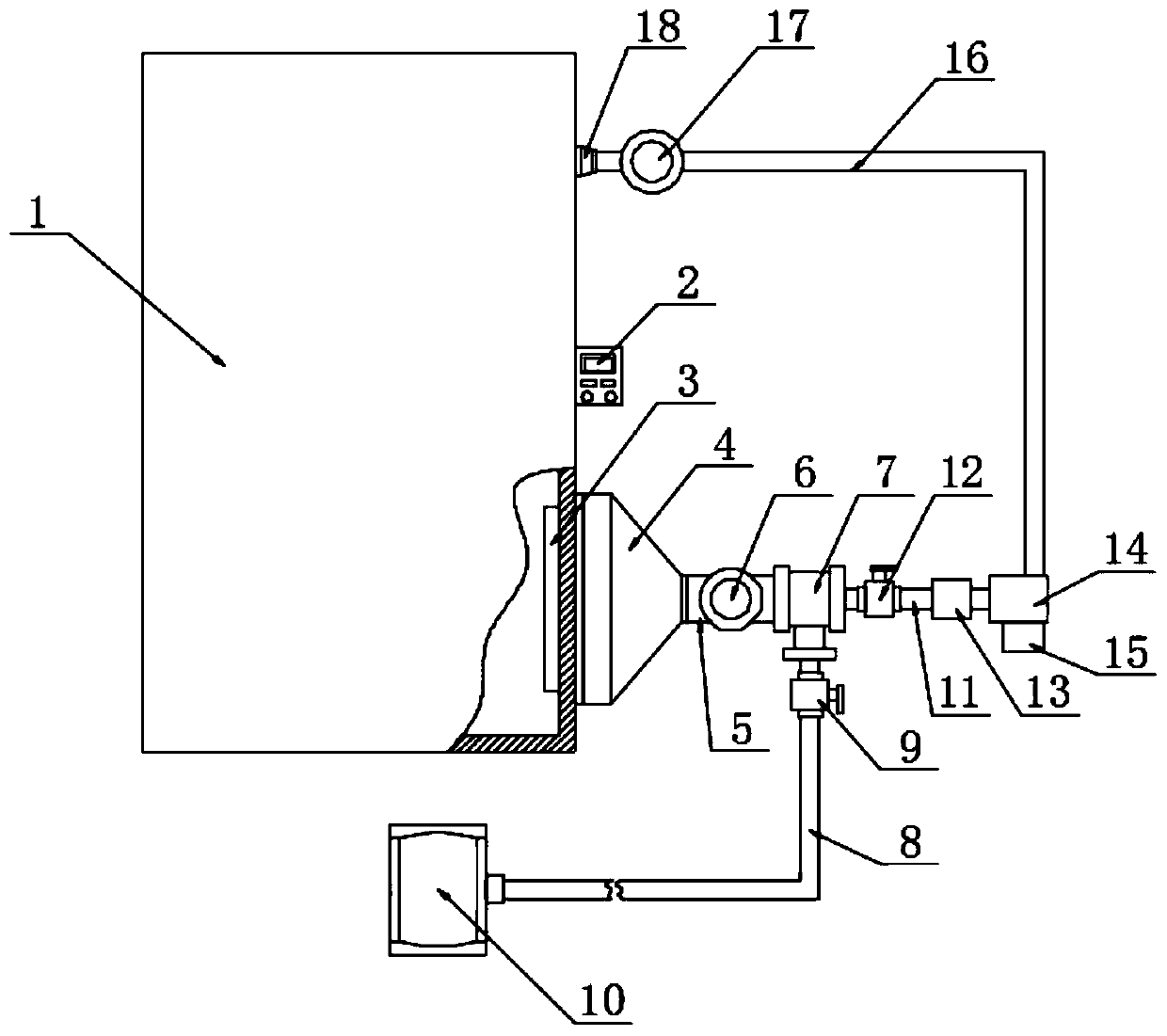
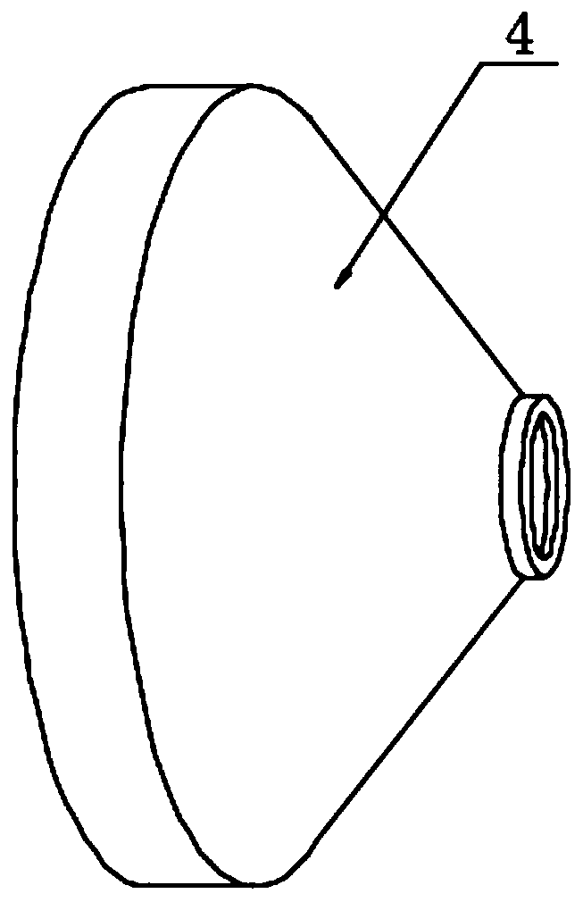
[0031] Refer to the attached Figure 1-7, a computer waste heat utilization device in this embodiment, comprising a main chassis 1, the outer wall of the rear wall heat exhaust hole of the main chassis 1 is equipped with a draft hood 4, and the inner wall of the main chassis 1 corresponds to the inner side of the port of the draft hood 4 Connected with a network frame 3, the inside of the networ...


PUM


Abstract

The embodiment of the invention discloses a computer waste heat utilization device and method. Specifically, the invention relates to the field of computers, main case, an air inducing cover is mounted on the outer wall of a heat discharging hole in the rear wall of the main case; one end of the air inducing cover is connected with a first air pipe; one end of the first air pipe is connected to the air inlet end of the first negative pressure fan; the air outlet end of the first negative pressure fan is connected with a three-way pipe through a pipe body, one port of the three-way pipe is connected with a second air pipe, one end of the second air pipe is connected with a first waste heat utilization mechanism, and the other port of the three-way pipe is connected with a second waste heatutilization mechanism. According to the invention, the utilization of waste heat can be regulated and controlled according to season changes; when the weather is cold, the waste heat is utilized through the first waste heat utilization mechanism, and when the weather is proper or hot, the waste heat is utilized through the second waste heat utilization mechanism, the interior of the mainframe boxcan be cooled conveniently in the using process, and the service life of the mainframe box is prolonged.

Description

technical field [0001] The embodiments of the present invention relate to the field of computers, and in particular to a computer waste heat utilization device and utilization method. Background technique [0002] Existing computer can produce a large amount of heat when working, and these heats are all discharged from computer case by the cooling device of computer, at first because the working frequency of computer is low, some working elements of computer, as central processing unit, graphics card chip The calorific value is small. With the upgrading of computer chips, the operating frequency of the central processing unit, graphics card chip and other working components is constantly increasing, and the calorific value is also increasing. The large amount of waste heat generated in this way is discharged from the computer. It is a kind of energy waste. [0003] The existing technology has the following disadvantages: the existing computer waste heat utilization device i...

Claims


Application Information

Patent Timeline
Patent Type & Authority Applications(China)
IPC IPC(8): G06F1/18G06F1/20
CPCG06F1/183G06F1/206
Inventor 郜东瑞王征炬周辉冯李逍彭茂琴张云霞张永清陈海宁
Owner CHENGDU UNIV OF INFORMATION TECH
Why Eureka
Try Eureka