Visual identification method for water pump impeller ring

A visual recognition and mouth ring technology, applied in image data processing, instruments, calculations, etc., can solve the problems of reduced efficiency of repeated operations, large positioning errors, and difficulty in ensuring installation accuracy, so as to improve efficiency, facilitate grasping, and avoid artificial effect of factors

Active Publication Date: 2020-05-15
WUHU HIT ROBOT TECH RES INST
View PDF4 Cites 4 Cited by
  • Summary
  • Abstract
  • Description
  • Claims
  • Application Information

AI Technical Summary

Problems solved by technology

[0003]When manually installing the mouth ring, the positioning error is large, the efficiency of

Method used


Image

  • Visual identification method for water pump impeller ring
  • Visual identification method for water pump impeller ring
  • Visual identification method for water pump impeller ring

Examples


Embodiment Construction

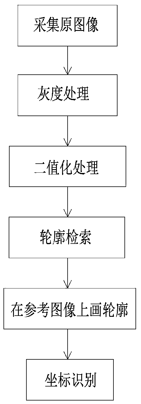
[0026] Such as figure 1 As shown, the present invention provides a visual recognition method for a water pump mouth ring, comprising the following steps:

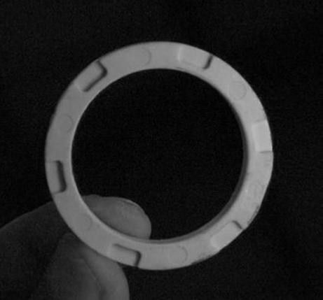
[0027] S1, combine figure 2 As shown, the original image of the horizontal plane of the water pump mouth ring is collected by an industrial camera;

[0028] S2, combine image 3 As shown, convert the collected original image into a grayscale image;

[0029] S3. Perform binarization and morphological processing on the grayscale image to obtain a visualized image;

[0030] S4. Retrieve the contour set of the visualized image, traverse all the contours, and eliminate the disturbing contours according to the contour size threshold method; enclose the filtered contour set with a minimum circle, and obtain the center and radius parameters of the circle surrounded by each contour;

[0031] S5, combine Figure 4 and Figure 5 As shown, create a reference image with the same size as the original image and a gray value of 0, d...


PUM


Abstract

The invention discloses a visual identification method for a water pump impeller ring. The method comprises the following steps: S1, collecting an original image of a water pump impeller ring horizontal plane by using an industrial camera; S2, converting the collected original image into a grayscale image; S3, performing binarization and morphological processing on the grayscale image to obtain avisual image; S4, performing contour set retrieval on the visual image, and traversing all contours; S5, creating a reference image with the same size as the original image and a gray value of 0, drawing a bounding circle of each contour in the step S4 on the reference image, and drawing each contour to obtain accurate contour information; S6, calculating the angle relation of the circle center ofeach contour surrounding circle obtained by the reference image based on the circle center of the contour surrounding circle obtained by the original image, and converting the pixel coordinates of the circle center into a robot coordinate system. By means of the method, the water pump impeller ring can be accurately and rapidly recognized, human factors are avoided, efficiency is improved, and subsequent grabbing of a robot is facilitated.

Description

technical field [0001] The invention relates to the technical field of water pump manufacturing, in particular to a visual identification method for a water pump mouth ring. Background technique [0002] In the pump body manufacturing industry, the mouth ring is also called the sealing ring, and some of them are also called the wear ring. The mouth ring is divided into a front mouth ring (at the impeller suction port) and a rear mouth ring (at the back of the impeller). The function of the front orifice is to separate the high-pressure area and the low-pressure area in the pump to prevent a large amount of liquid from flowing from the high-pressure area to the low-pressure area; the rear orifice ring is generally used in combination with a balance hole to balance the axial force and reduce the pressure of the seal chamber. The installation of the mouth ring is generally placed manually. During the installation, it is necessary to ensure the accuracy of the position and angl...

Claims


Application Information

Patent Timeline
IPC IPC(8): G06T7/62G06T7/66G06T7/13G06T5/30
CPCG06T7/62G06T7/66G06T7/13G06T5/30G06T2207/10004
Inventor 徐昌军于福才陈健高云峰曹雏清
Owner WUHU HIT ROBOT TECH RES INST
Why Eureka
Try Eureka