Fault detection device, laser processing system and fault detection method
A fault detection and laser technology, which is applied in the direction of measuring devices, laser welding equipment, metal processing equipment, etc., can solve the problems of peripheral device damage, processing laser output energy, etc., and achieve high reliability.
- Summary
- Abstract
- Description
- Claims
- Application Information
AI Technical Summary
Problems solved by technology
Method used
Image

Examples
Embodiment approach 1
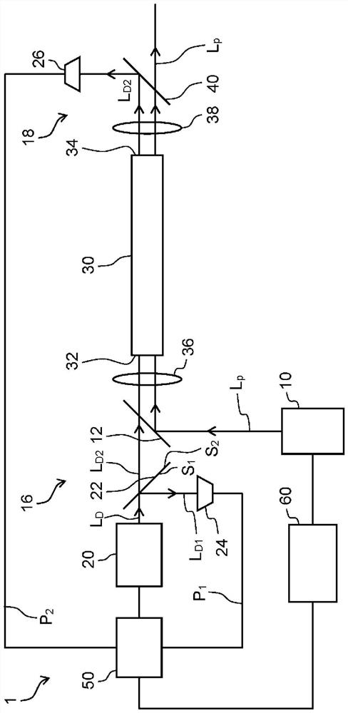
[0031] refer to figure 1 Embodiment 1 of the fault detection device 1 according to the present disclosure will be described. figure 1 It is a block diagram showing a schematic configuration of the failure detection device 1 according to the present disclosure. Roughly speaking, the fault detection device 1 according to Embodiment 1 is as follows: figure 1 As shown, it includes a processing laser light source 10, a detection laser light source 20, a half mirror 22 (beam splitter), an optical fiber 30 (also called a process fiber or a transmission fiber), first and second photodetectors 24, 26 (light receivers) ) and the failure determination unit 50 (only referred to as the determination unit). In addition, the laser processing system according to the present disclosure includes a system control unit 60 electrically connected to the processing laser light source 10 and the failure determination unit 50 of the fault detection device 1 . The laser processing system includes a ...
Embodiment approach 2
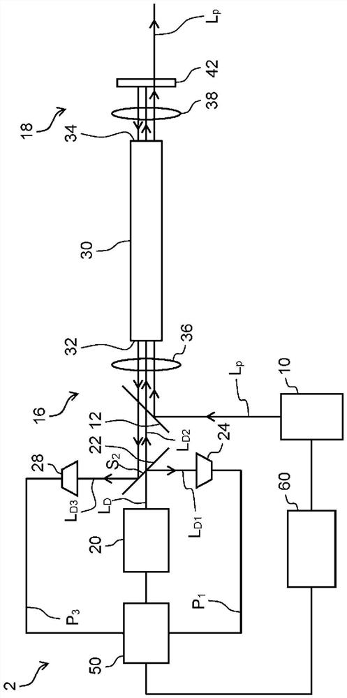
[0042] refer to figure 2 Embodiment 2 of the fault detection device 2 according to the present disclosure will be described. figure 2 It is a block diagram showing a schematic configuration of the fault detection device 2 according to the present disclosure. Roughly speaking, the fault detection device 2 according to the second embodiment includes a second light L for detecting the second part of light L reciprocating through the optical fiber 30 instead of the second photodetector 26 . D2 The third photodetector 28 has the same configuration as that of Embodiment 1 except for this point, and therefore descriptions of overlapping points will be omitted. The third photodetector 28 is housed in the first storage chamber 16 .
[0043] Roughly speaking, the fault detection device 2 according to the second embodiment includes the processing laser light source 10, the detection laser light source 20, the half mirror 22 (beam splitter), the optical fiber 30, and the first photode...
Embodiment approach 3
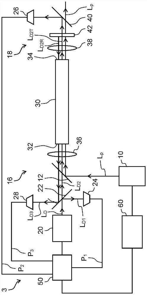
[0053] refer to image 3 Embodiment 3 of the fault detection device 3 according to the present disclosure will be described. image 3 It is a block diagram showing a schematic configuration of the failure detection device 3 according to the present disclosure. Roughly speaking, the fault detection device 3 according to Embodiment 3 is equipped with the third photodetector 28 of Embodiment 2 in addition to the second photodetector 26 of Embodiment 1, and has the same characteristics as Embodiment 1 except this point. The structure is the same, so descriptions related to overlapping points are omitted.
[0054] Roughly speaking, the fault detection device 3 according to the third embodiment includes the processing laser light source 10, the detection laser light source 20, the half mirror 22 (beam splitter), the optical fiber 30, and the first photodetector 24 ( photoreceiver) and the failure judging unit 50 (judging unit). Their structures and functions are the same as those...
PUM
 Abstract
Description
Claims
Application Information
 - R&D Engineer
- R&D Manager
- IP Professional
- Industry Leading Data Capabilities
- Powerful AI technology
- Patent DNA Extraction
Browse by: Latest US Patents, China's latest patents, Technical Efficacy Thesaurus, Application Domain, Technology Topic.
© 2024 PatSnap. All rights reserved.Legal|Privacy policy|Modern Slavery Act Transparency Statement|Sitemap