Fault detection device, laser machining system and fault detection method

A fault detection and laser technology, which is applied in the direction of measuring devices, laser welding equipment, metal processing equipment, etc., can solve the problems of peripheral device damage, processing laser output energy, etc., and achieve high reliability.

Active Publication Date: 2020-05-15
PANASONIC INTELLECTUAL PROPERTY MANAGEMENT CO LTD
View PDF13 Cites 1 Cited by
  • Summary
  • Abstract
  • Description
  • Claims
  • Application Information

AI Technical Summary

Problems solved by technology

For such an optical fiber, if the optical fiber is disconnected while the processing laser is being transmitted, the output energy of the processing laser will be large, which may cause damage to peripheral devices represented by the coating resin of the optical fiber.

Method used


Image

  • Fault detection device, laser machining system and fault detection method
  • Fault detection device, laser machining system and fault detection method
  • Fault detection device, laser machining system and fault detection method

Examples


Embodiment approach 1

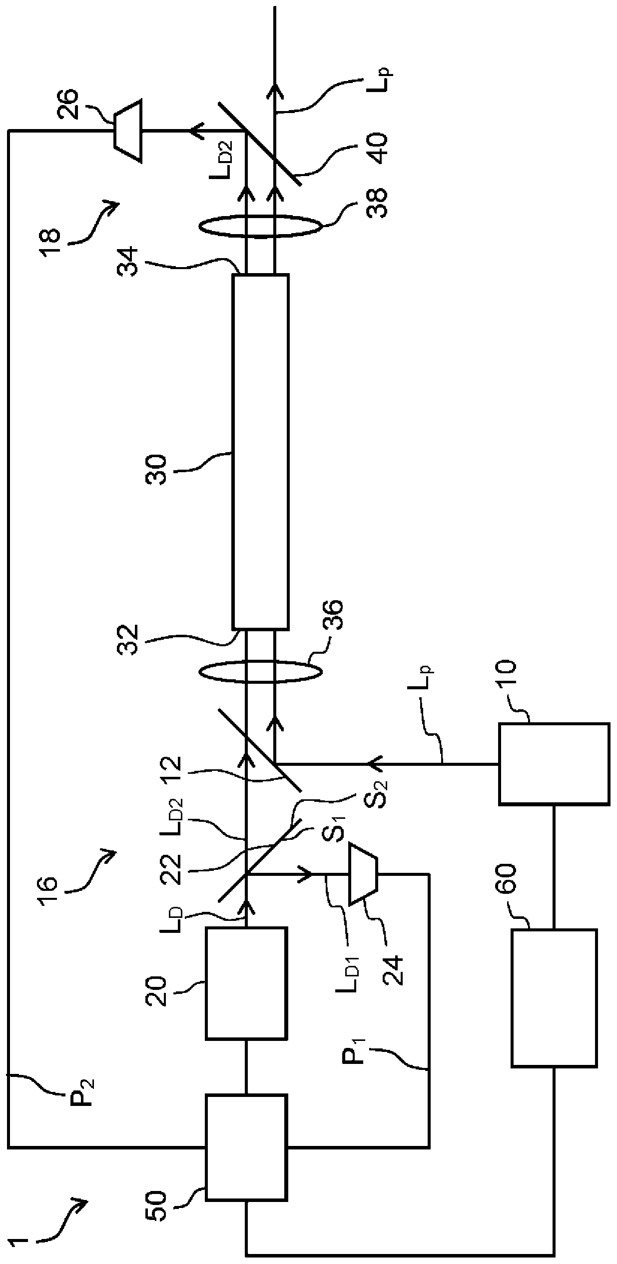
[0031] reference figure 1 The first embodiment of the failure detection device 1 according to the present disclosure will be described. figure 1 It is a block diagram showing a schematic configuration of the failure detection device 1 according to the present disclosure. Roughly speaking, the failure detection device 1 according to the first embodiment is as figure 1 As shown, it is equipped with a processing laser light source 10, a detection laser light source 20, a half mirror 22 (spectroscope), an optical fiber 30 (also referred to as a process fiber or a transmission fiber), and first and second photodetectors 24, 26 (light receivers) ) And the failure determination unit 50 (referred to as the determination unit only). In addition, the laser processing system according to the present disclosure includes a system control unit 60 electrically connected to the processing laser light source 10 and the failure determination unit 50 of the failure detection device 1. The laser p...

Embodiment approach 2

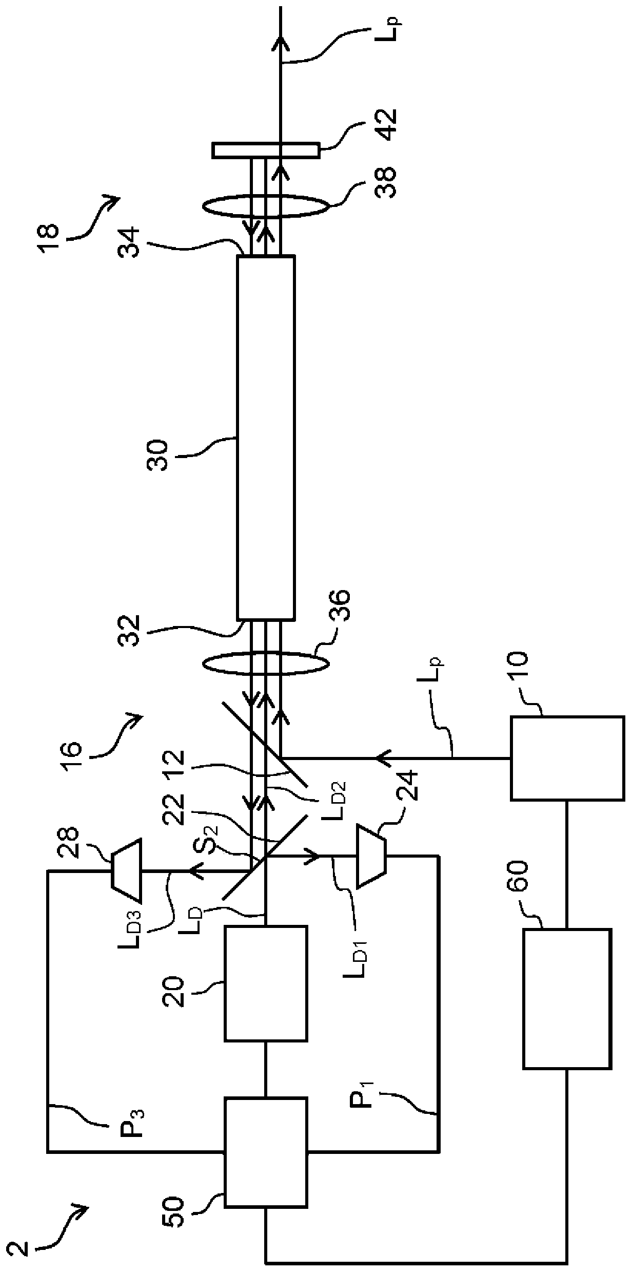
[0042] reference figure 2 The second embodiment of the failure detection device 2 according to the present disclosure will be described. figure 2 It is a block diagram showing a schematic configuration of the failure detection device 2 according to the present disclosure. Roughly speaking, the failure detection device 2 according to the second embodiment replaces the second photodetector 26 and includes a second partial light L that detects reciprocating in the optical fiber 30 D2 Except for this point, the third photodetector 28 has the same configuration as that of the first embodiment, so the description of the overlapping points is omitted. The third photodetector 28 is housed in the first storage chamber 16.

[0043] Roughly speaking, the failure detection device 2 according to the second embodiment includes a processing laser light source 10, a detection laser light source 20, a half mirror 22 (spectroscope), an optical fiber 30, and a first photodetector 24 as in the firs...

Embodiment approach 3

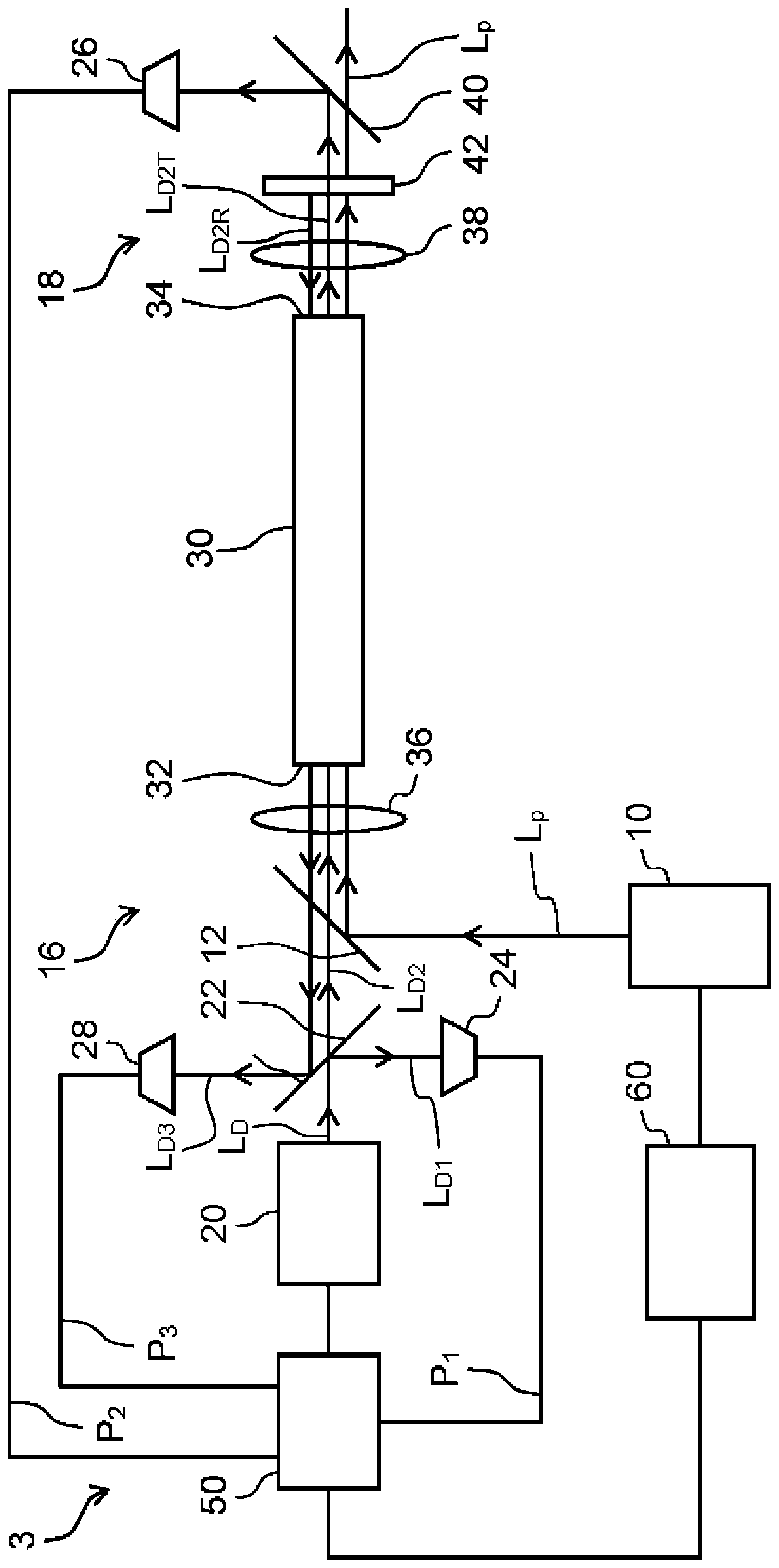
[0053] reference image 3 The third embodiment of the failure detection device 3 according to the present disclosure will be described. image 3 It is a block diagram showing a schematic configuration of the failure detection device 3 according to the present disclosure. Roughly speaking, the failure detection device 3 according to the third embodiment includes the third photodetector 28 of the second embodiment in addition to the second photodetector 26 of the first embodiment. In addition to this point, it is similar to that of the first embodiment. The structure is the same, so the description about the overlapping points is omitted.

[0054] Roughly speaking, the failure detection device 3 according to the third embodiment includes a processing laser light source 10, a detection laser light source 20, a half mirror 22 (spectroscope), an optical fiber 30, and a first photodetector 24 as in the first embodiment. The light receiver) and the failure determination unit 50 (determi...


PUM


Abstract

This fault detection device (1) is provided with: a machining laser light source (10) which emits machining laser light; a detection laser light source (20) which emits detection laser light; a spectroscope (22) which divides the detection laser light into first partial light and second partial light; a first light receiver (24) which measures the intensity of the first partial light of the detection laser light; an optical fiber (30) which transmits the second partial light of the detection laser light and the machining laser light; a second light receiver (26) which measures the intensity ofthe second partial light transmitted through the optical fiber; and a determination unit (50) which determines whether there is a defect in the optical fiber on the basis of the relative ratio between the intensities of the first and second partial light respectively measured by the first and second light receivers.

Description

Technical field [0001] The present disclosure relates to an optical fiber failure detection device, a laser processing system, and a failure detection method, and to an optical fiber failure detection device, a laser processing system, and a failure detection method that transmit a particularly high output processing laser. Background technique [0002] The following laser processing systems are widely used: high-output processing laser light from a direct diode laser (DDL) light source is transmitted to the processing head via an optical fiber, and the light is concentrated and irradiated, thereby welding, fusing and perforating the workpiece (workpiece) Wait. For such an optical fiber, if the optical fiber is disconnected while the processing laser is being transmitted, the output energy of the processing laser will be large, which may cause damage to peripheral devices represented by the coating resin of the optical fiber. Therefore, in a laser processing system using a high-...

Claims


Application Information

Patent Timeline
Patent Type & Authority Applications(China)
IPC IPC(8): G01M11/00B23K26/00B23K26/064
CPCB23K26/00B23K26/064G01M11/00
Inventor 石川谅山下隆之长安同庆星野贤二山口秀明加藤直也堂本真也江泉清隆
Owner PANASONIC INTELLECTUAL PROPERTY MANAGEMENT CO LTD
Why Eureka
Try Eureka