Disconnection detecting device, signal processing unit and disconnection detection method

A technology for signal processing unit and disconnection detection, which is applied in measurement devices, electrical measurement, short-circuit testing, etc., and can solve the problems that the signal processing unit cannot normally receive emergency information, and the signal processing cannot be performed.

Active Publication Date: 2018-10-09
YAMAHA CORP
View PDF8 Cites 1 Cited by
  • Summary
  • Abstract
  • Description
  • Claims
  • Application Information

AI Technical Summary

Problems solved by technology

Although the transmission line from the signal processing unit to the communication unit is normal, in the case of an abnormality in the reception line from the communication unit to the signal processing unit, the signal processing unit cannot receive emergency information normally, whereby the signal processing cannot be performed later. stage is executed in the signal processing unit

Method used


Image

  • Disconnection detecting device, signal processing unit and disconnection detection method
  • Disconnection detecting device, signal processing unit and disconnection detection method
  • Disconnection detecting device, signal processing unit and disconnection detection method

Examples


no. 1 example

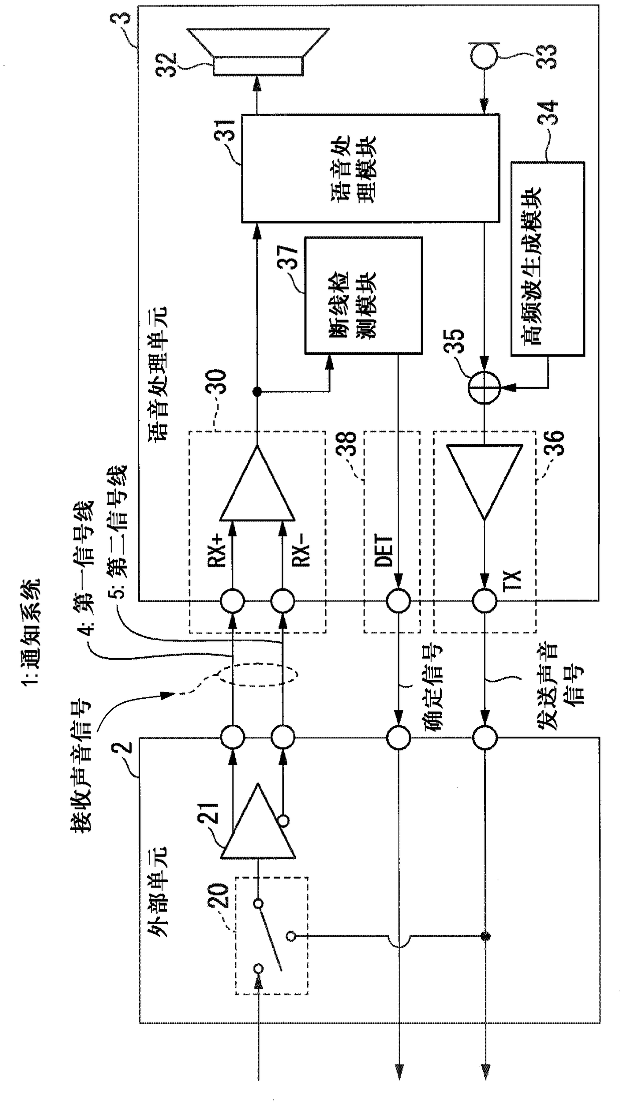
[0027] First, a first embodiment will be described. figure 1 It is a block diagram showing the configuration of the notification system 1 . Such as figure 1 As shown, the notification system 1 includes an external unit 2 and a speech processing unit 3 .

[0028] A sound signal is sent between the external unit 2 and the speech processing unit 3 . The external unit 2 receives, for example, a transmission sound signal from the speech processing unit 3 and sends it to a control center (not shown), and receives a signal indicating an instruction from the control center to output it to the speech processing unit 3 as a reception sound signal. Therefore, the external unit 2 is a communication processing unit.

[0029] The external unit 2 includes a switch 20 and a differential output module 21 .

[0030] Based on the control signal from the voice processing unit 3 , the switch 20 switches the signal to be input into the differential output module 21 to any one of the signal from...

no. 2 example

[0098] Next, a second embodiment will be described. Figure 6 is a block diagram showing the composition of the notification system 1 according to the second embodiment. In the following description, similar reference numerals are given to similar configurations to those of the first embodiment, and descriptions thereof are omitted.

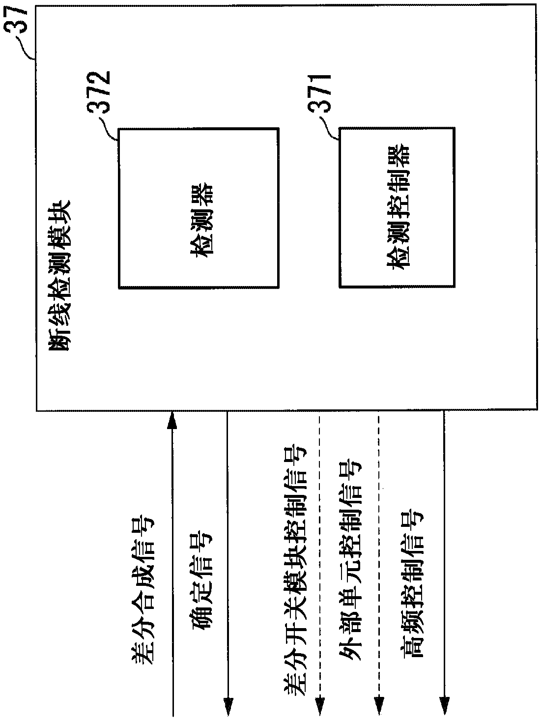
[0099] In the second embodiment, the disconnection detection module 37 determines whether the speaker module 32 and the microphone module 33 fail (performs failure determination). The disconnection detection module 37 may determine failure of the speaker module 32 and the microphone module 33 only, or may determine failure of the speaker module 32 and the microphone module 33 in addition to the determination made in the first embodiment. In the case where the disconnection detection module 37 determines failures of the speaker module 32 and the microphone module 33 in addition to the determination made in the first embodiment, the disconnection ...


PUM


Abstract

The invention relates to a disconnection detecting device, a signal processing unit and a disconnection detection method. The disconnection detecting device includes a confirmation signal outputting module configured to cause a transmission sound signal to be outputted from a signal processing unit, and a detector. The transmission sound signal includes a confirmation signal having a frequency that differs from a frequency band for use in communicating information contained in the transmission sound signal that is sent from the signal processing unit to a communication unit. The detector is configured to detect whether or not a disconnection is occurring in connection wires based on the transmission sound signal including the confirmation signal that is returned from the communication unitto the signal processing unit via the connection wires.

Description

technical field [0001] The invention relates to a wire break detection device, a signal processing unit and a wire break detection method. Background technique [0002] Typically, there is a notification system that notifies emergency situations. In these notification systems, for example, a communication unit and a signal processing unit are connected via a connection line. Although the transmission line from the signal processing unit to the communication unit is normal, in the case of an abnormality in the reception line from the communication unit to the signal processing unit, the signal processing unit cannot receive emergency information normally, whereby the signal processing cannot be performed later. Phases are executed in the signal processing unit. [0003] Incidentally, for example, Patent Document 1 describes a detection method as a method for detecting abnormality in such a notification system. In the notification system for notifying an emergency described...

Claims


Application Information

Patent Timeline
Patent Type & Authority Applications(China)
IPC IPC(8): H04R29/00G01R31/58
CPCH04R29/001H04R2420/05G08B29/04G01R31/54G01R31/52G01R31/58H04R1/2803
Inventor 村木保之
Owner YAMAHA CORP
Why Eureka
Try Eureka