Drive system of mechanical arm

A technology of mechanical arm and driving system, which is applied in the direction of manipulator, program control manipulator, claw arm, etc., which can solve the problems of inconvenient movement, inconvenient use of driving mechanism, and inability to meet different use requirements, so as to achieve convenient installation and disassembly, convenient movement and The effect of height adjustment and simple structure

Inactive Publication Date: 2020-05-19
罗厚镇
View PDF0 Cites 3 Cited by
  • Summary
  • Abstract
  • Description
  • Claims
  • Application Information

AI Technical Summary

Problems solved by technology

[0004] The purpose of the present invention is to solve the shortcomings of the existing drive mechanism, which is inconvenient to use, mo...

Method used


Image

  • Drive system of mechanical arm
  • Drive system of mechanical arm
  • Drive system of mechanical arm

Examples


Embodiment 1

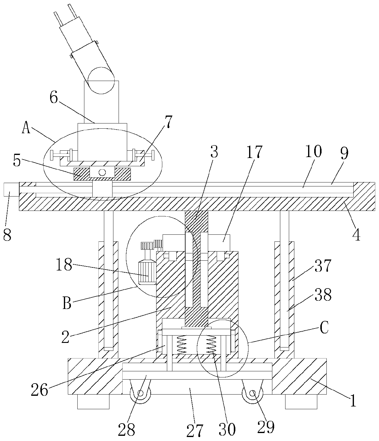
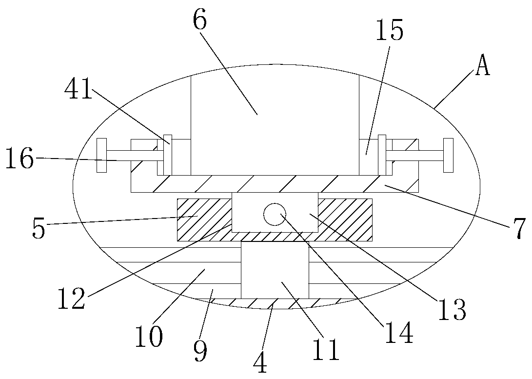
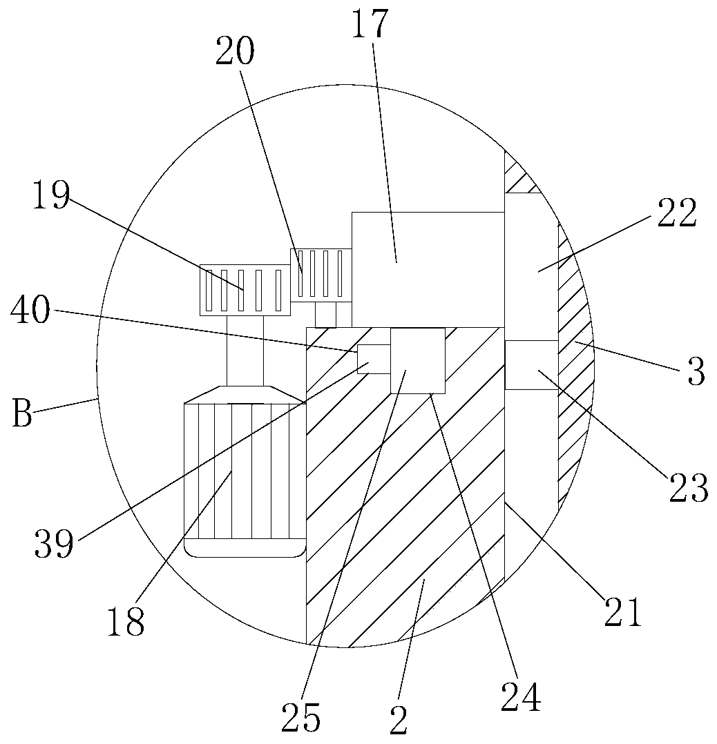
[0031] refer to Figure 1-5 , a driving system of a mechanical arm, comprising a base 1 and a mechanical arm 6, a column 2 is fixedly installed on the top of the base 1, a thrust rod 3 is movably connected to the top of the column 2, and a horizontal adjustment mechanism is fixedly installed on the top of the thrust rod 3, A vertical adjustment mechanism is slidingly installed on the horizontal adjustment mechanism, and a placement tray 7 is slidingly installed on the longitudinal adjustment mechanism. Bottom groove 27, base plate 28 is slidably installed in bottom groove 27, and four universal wheels 29 are fixedly installed on the bottom of base plate 28, and the top of column 2 is provided with guide hole 21, and thrust rod 3 is connected with guide hole 21 slidingly, and column 2 The top of the shaft is rotated with an internally threaded gear 17, and the outside of the thrust rod 3 is provided with an external thread, and the external thread is threaded with the inner rin...

Embodiment 2

[0042] refer to Figure 1-5 , a driving system of a mechanical arm, comprising a base 1 and a mechanical arm 6, the top of the base 1 is fixedly installed with a column 2 by welding, the top of the column 2 is movably connected with a thrust rod 3, and the top of the thrust rod 3 is fixedly installed with a Horizontal adjustment mechanism, the vertical adjustment mechanism is slidably installed on the horizontal adjustment mechanism, and the placement plate 7 is slidably installed on the longitudinal adjustment mechanism. There is a bottom groove 27 at the bottom of the bottom groove, and a base plate 28 is slidably installed in the bottom groove 27. Four universal wheels 29 are fixedly installed on the bottom of the base plate 28 by welding. The top of the column 2 is provided with a guide hole 21, and the thrust rod 3 and the guide hole 21 sliding connection, the top of the column 2 is rotated with an internally threaded gear 17, the outer side of the thrust rod 3 is provide...


PUM


Abstract

The invention belongs to the technical field of drive structures of mechanical arms, in particular to a drive system of a mechanical arm. In order to solve the problem that different use needs cannotbe met as an existing drive mechanism is inconvenient in use, is mostly fixed on one position, and is inconvenient to move, the invention discloses the following scheme: the drive system comprises a base and a mechanical arm, wherein the top of the base is fixedly equipped with a stand column; the top of the stand column is movably connected with a pushing rod; the top of the pushing rod is fixedly equipped with a transverse regulating mechanism; a longitudinal regulating mechanism is slidably mounted on the transverse regulating mechanism; a placing disc is slidably mounted on the longitudinal regulating mechanism; a placing slot is formed in the top of the placing disc; the mechanical arm is adaptive to the placing slot; a bottom slot is formed in the bottom of the base; and a bottom plate is slidably mounted in the bottom slot. The drive system is simple in structure, is convenient to operate, can conveniently move and perform height regulation on a drive structure body, can improvestability while used, and can meet different use needs.

Description

technical field [0001] The invention belongs to the technical field of driving structure of a mechanical arm, and in particular relates to a driving system of a mechanical arm. Background technique [0002] The mechanical arm plays an important role in industrial production. Usually, the mechanical arm is required to transfer or clamp the workpiece in the processing equipment. In order to expand the range of motion of the mechanical arm, the mechanical arm is usually installed on the driving structure. Driving the mechanical arm through the driving structure can expand the range of motion of the mechanical arm and improve the use efficiency. [0003] The existing driving mechanism is inconvenient to use, mostly fixed at one position, inconvenient to move, and unable to meet the needs of different uses. Contents of the invention [0004] The purpose of the present invention is to solve the shortcomings of the existing drive mechanism, which is inconvenient to use, mostly f...

Claims


Application Information

Patent Timeline
IPC IPC(8): B25J5/02B25J9/00B25J18/00
CPCB25J5/02B25J9/00B25J9/0009B25J18/00
Inventor 罗厚镇
Owner 罗厚镇
Why Eureka
Try Eureka