Speed-adjustable powder discharging device

An adjustable, powder technology, applied in solid materials, packaging, packaging protection and other directions, can solve the problems of difficult to control the feeding speed, the wet powder can not meet expectations, etc., to achieve compact structure, convenient operation, avoid dust. Effect

Active Publication Date: 2020-05-19
JIANGNAN UNIV +1
View PDF3 Cites 0 Cited by
  • Summary
  • Abstract
  • Description
  • Claims
  • Application Information

AI Technical Summary

Problems solved by technology

The traditional powder feeding mechanism usually adopts screw feeding. This feeding method often fails to achieve the expected effect on damp powder, and the feeding speed is difficult to control.

Method used


Image

  • Speed-adjustable powder discharging device
  • Speed-adjustable powder discharging device
  • Speed-adjustable powder discharging device

Examples


Embodiment Construction

[0019] The specific implementation manner of the present invention will be described below in conjunction with the accompanying drawings.

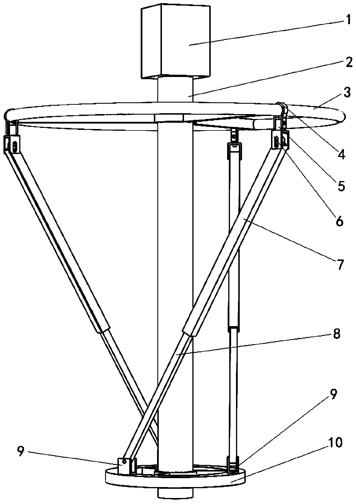
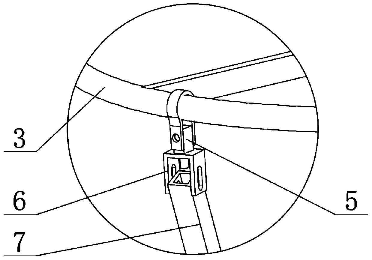
[0020] Such as Figure 1-Figure 3 As shown, the speed-adjustable powder feeding device of this embodiment includes an upper ring body 3 and a lower ring body 10, and the inner rings of the upper ring body 3 and the lower ring body 10 are respectively sleeved on the upper end and the lower end of the rotating shaft 2, Between the upper ring body 3 and the lower ring body 10, a plurality of connecting rod assemblies with the same inclination angle are arranged, and the upper and lower ends of the connecting rod assemblies are respectively connected with the outer ring of the upper ring body 3 and the outer ring of the lower ring body 10 to form Spiral stirring rod structure.

[0021] The connecting rod assembly includes an upper rod 7 and a lower rod 8 with one end extending into the upper rod 7 and slidingly fitted therewith.

[0022] The...


PUM


Abstract

The invention relates to a speed-adjustable powder discharging device. The speed-adjustable powder discharging device comprises a rotating shaft, an upper ring body and a lower ring body, wherein theupper ring body and the lower ring body are arranged on the rotating shaft in a sleeving mode, and a plurality of connecting rod assemblies which have the same inclination angle and form a spiral stirring rod structure are arranged between the upper ring body and the lower ring body. Each connecting rod assembly comprises upper rods and lower rods, wherein one end of each lower rod extends into the corresponding upper rod to be in sliding fit with the upper rod. A plurality of sliding rings are evenly arranged on the outer ring of the upper ring body in the circumferential direction, and the sliding rings are connected with upper hinged supports arranged at the top ends of the upper rods through connecting blocks; and a plurality of lower hinged supports corresponding to the sliding ringsare evenly arranged on the lower ring body in the circumferential direction, and the bottom ends of the lower rods are connected with the lower ring body through the lower hinged supports. According to the speed-adjustable powder discharging device, the relative positions of the upper rod and the lower rod are controlled by adjusting the rotating angles of the upper hinged supports and the lower hinged supports, so that the included angles between the lower rods and the horizontal direction are adjusted, and the powder stress and the discharging speed are controlled. The problems of dust raising and the like caused by controlling the discharging speed by adjusting the rotating speed of the motor are avoided, and the device is particularly suitable for efficient discharging of the damp powder.

Description

technical field [0001] The invention relates to the technical field of powder feeding devices, in particular to a speed-adjustable powder feeding device. Background technique [0002] In the field of industrial automation, it is often necessary to weigh and pack the powder in the hopper of the packaging machine. The traditional powder feeding mechanism usually adopts screw feeding. This feeding method often fails to achieve the expected effect on damp powder, and the feeding speed is difficult to control. Contents of the invention [0003] In view of the shortcomings in the above-mentioned existing production technology, the applicant provides a speed-adjustable powder feeding device with a reasonable structure, which is suitable for making the wet powder fall smoothly from the hopper and realizing the control of the falling speed. [0004] The technical scheme adopted in the present invention is as follows: [0005] A speed-adjustable powder feeding device, comprising a...

Claims


Application Information

Patent Timeline
Patent Type & Authority Applications(China)
IPC IPC(8): B65B1/04B65B57/00
CPCB65B1/04B65B57/00
Inventor 王琨王诚意宁萌
Owner JIANGNAN UNIV
Why Eureka
Try Eureka