An electromagnetic lock working power reduction circuit

A technology of working power and electromagnetic lock, which is applied to circuits, electromagnets, electromagnets with armatures, etc., can solve the problems of reducing maintenance power and high temperature of electromagnetic locks, and achieves the advantages of reducing working temperature, increasing cost and simple circuit design. Effect

Active Publication Date: 2022-07-01
LANZHOU INST OF PHYSICS CHINESE ACADEMY OF SPACE TECH
View PDF16 Cites 0 Cited by
  • Summary
  • Abstract
  • Description
  • Claims
  • Application Information

AI Technical Summary

Problems solved by technology

[0003] In view of this, the present invention provides an electromagnetic lock working power reduction circuit, which can not only meet the requirement of high power input when the electromagnetic lock is started, but also reduce the required maintenance power after the electromagnetic lock is started, and solve the problem of electromagnetic lock The temperature of the electromagnetic lock is too high caused by the high power input after the lock is activated

Method used


Image

  • An electromagnetic lock working power reduction circuit

Examples


Embodiment Construction

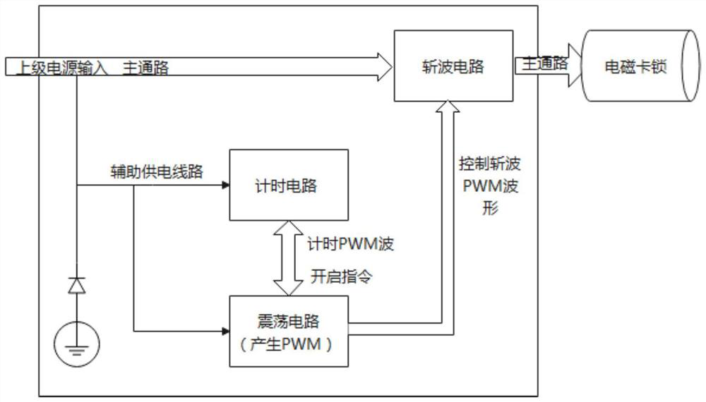
[0016] The present invention will be described in detail below with reference to the accompanying drawings and embodiments.

[0017] The invention provides an electromagnetic lock working power reduction circuit, such as figure 1 As shown, it includes an oscillator circuit, a timing circuit and a chopper circuit; the bus power supply is connected to the chopper circuit, and the chopper circuit is connected to the electromagnetic lock. Circuit and timing circuit, the oscillator circuit generates two PWM waves successively, the first PWM wave is sent to the timing circuit, and the timing circuit starts timing; after the timing reaches the set time, the timing circuit sends the second PWM wave to the oscillator circuit to start command; the oscillation circuit sends the second PWM wave to the chopper circuit, so that the DC power supply waveform output before the chopper circuit becomes a PWM waveform; the current at the input terminal of the electromagnetic lock forms a pulse sq...


PUM


Abstract

The invention discloses an electromagnetic lock working power reduction circuit, which includes an oscillation circuit, a timing circuit and a chopper circuit; a busbar power supply is connected to the chopper circuit, the chopper circuit is connected to the electromagnetic lock, and the oscillation circuit and the timing circuit are driven by voltage divider from the busbar power supply The oscillation circuit generates two PWM waves successively, and the first PWM wave is sent to the timing circuit. After the timing reaches the set time, the timing circuit sends the start command of the second PWM wave to the oscillation circuit; the oscillation circuit sends the second PWM wave to the timing circuit. The wave is sent to the chopper circuit, so that the DC power supply waveform output before the chopper circuit becomes a PWM waveform; the current at the input terminal of the electromagnetic lock forms a pulsed square wave; whenever the square wave of the power input is turned off, the electromagnetic lock will use its magnetic material. The stored energy is released to maintain its own work; the invention can not only meet the requirement of high power input when the electromagnetic lock is started, but also reduce the maintenance power after the electromagnetic lock is started.

Description

technical field [0001] The invention belongs to the technical field of space electronic equipment, and in particular relates to an electromagnetic lock working power reduction circuit. Background technique [0002] Nuclear energy applications will play an increasingly important role in future deep space exploration missions. The safety rod driving mechanism is the key equipment of the space nuclear energy application system and the driving mechanism of the reactor safety rod system. The movement is transmitted from the initial position to the final position, and the compression spring matched with the rack is compressed to the working stroke. At this time, the electromagnetic lock is energized, the clutch is de-energized, and the rack head of the mechanism is locked, and the locked state is maintained for a long time to ensure the normal operation of the reactor. At the end of the reactor life or in an accident state, the electromagnetic lock is de-energized and the reactor...

Claims


Application Information

Patent Timeline
Patent Type & Authority Patents(China)
IPC IPC(8): H01F7/18E05B47/00
CPCH01F7/1816E05B47/0002H01F2007/1888E05B2047/0066
Inventor 陈鸿翔王雪松李家亮景春妍妥安平成明宇
Owner LANZHOU INST OF PHYSICS CHINESE ACADEMY OF SPACE TECH
Why Eureka
Try Eureka