Inorganic explosion-proof bridge bracket

A bridge and inorganic technology, applied in the field of inorganic explosion-proof bridge supports, can solve the problems of insignificant effect, waste of manpower and material resources, etc., to achieve strong structural ductility and elastic absorption capacity, prolong service life, good heat insulation and corrosion resistance sexual effect

Inactive Publication Date: 2018-06-12
成都煜萃科技有限公司
View PDF0 Cites 0 Cited by
  • Summary
  • Abstract
  • Description
  • Claims
  • Application Information

AI Technical Summary

Problems solved by technology

Most of the bridges are built on valleys or rivers. The bridge supports on the valleys have been subjected to wind erosion and wind impact for a long time, and the bridge supports on the rivers have been subjected to water erosion for a long time, so that th

Method used


Image

  • Inorganic explosion-proof bridge bracket
  • Inorganic explosion-proof bridge bracket

Examples


Embodiment 1

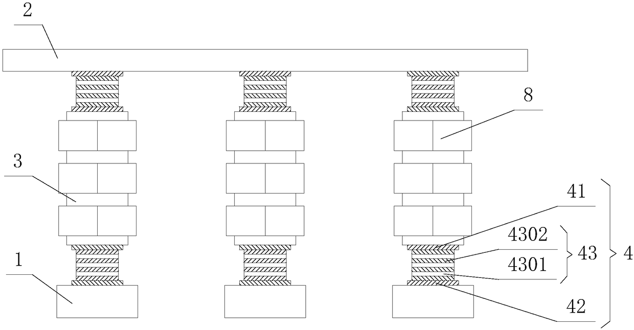
[0017] Such as figure 1 and figure 2 As shown, the inorganic explosion-proof bridge support provided in this embodiment includes a bridge pier 1, a bridge body 2 and a bridge pillar 3, and a composite connecting seat 4 is provided between the bridge pillar 3, the bridge pier 1 and the bridge body 2, and the composite connecting seat 4 It includes an upper sealing plate 41, a lower sealing plate 42 and a rubber bearing 43. The rubber bearing 43 is located between the upper sealing plate 41 and the lower sealing plate 42, and is bonded to the upper sealing plate 41 and the lower sealing plate 42. The rubber support 43 includes several layers of rubber protection layers 4301 and several layers of steel plate layers 4302, and several layers of rubber protection layers 4301 and several layers of steel plate layers 4302 are alternately overlapped, wherein the bottommost and topmost layers are both steel plate layers 4302, and the bridge pillars 3 and the bridge pier 1, the bottom ...

Embodiment 2

[0019] This embodiment is basically the same as Embodiment 1, except that the bridge pillar 3 is changed, and several fluorescent warning strips are uniformly arranged on the surface of the inorganic layer 6 of the bridge pillar 3 .

Embodiment 3

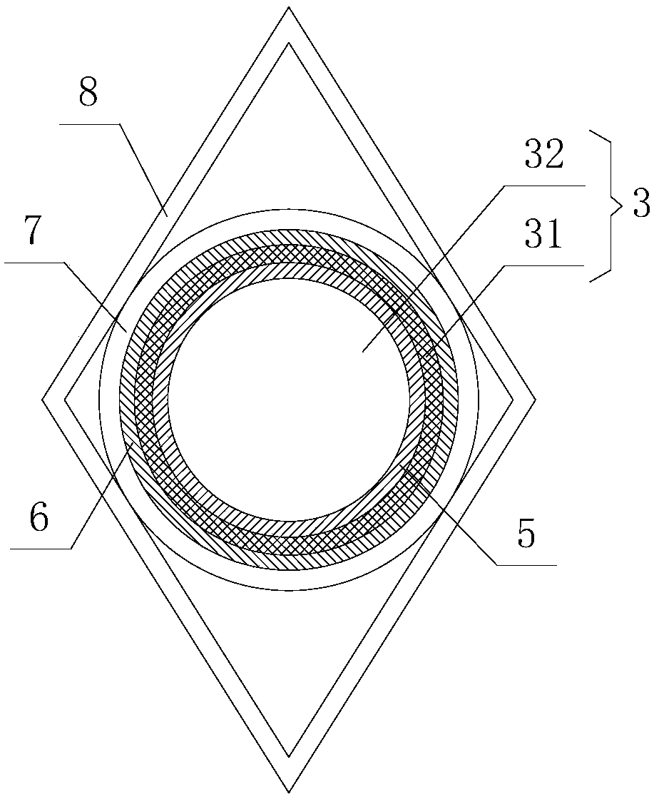
[0021] This embodiment is basically the same as Embodiment 1, except that the diversion housing 8 is changed, and an auxiliary reinforcing rib perpendicular to the inner wall of the diversion housing 8 is also provided between the inner wall of the diversion housing 8 and the outer wall of the bridge pillar 3, and The surface of the shunt casing 8 is coated with a corrosion-resistant layer.

[0022] The rubber support 43 in the composite connection seat 4 of the present invention is composed of several layers of rubber protection layers 4301 and several layers of steel plate layers 4302 alternately overlapping, which can increase the reliability of the rubber support 43. When the bridge vibrates, the composite connection seat 4 It can absorb vibration, so as to prevent the bridge pier 1 from being damaged by vibration; the included angle of the water flow or the wind impact direction of the diversion shell 8 can divert the water flow or wind force, reduce the impact force on th...


PUM


Abstract

The invention discloses an inorganic explosion-proof bridge bracket including bridge piers, a bridge body and bridge pillars. Composite connecting seats are fixed between the bridge pillars and the bridge piers and the bridge body. The bridge pillars include cylindrical steel bar skeletons. The inner surfaces of the steel bar skeletons are covered with barrier explosion-proof layers. The steel barskeletons are fully filled into concrete material. The outer wall surfaces of the bridge pillars are coated with an inorganic layer. A plurality of fixed mounting rings are arranged on the outer walls of the bridge pillars along the height direction of the bridge pillars. The two adjacent fixed mounting rings are sleeved with diamond-shaped split housings. The upper portion of the inner side of the split housing is connected with a fixed mounting ring, and the lower portion of the inner side of the split housing is connected with another fixed mounting ring. The inorganic explosion-proof bridge bracket is solid in structure, and good in corrosion resistance and impact resistance. The maintenance cost of the bridge pillars is reduced, and the service life of the bridge pillars is prolonged.

Description

technical field [0001] The invention belongs to the technical field of bridges, and in particular relates to an inorganic explosion-proof bridge bracket. Background technique [0002] With the development of the transportation industry, there are more and more bridge construction projects. The bracket method is one of the main construction methods for bridge construction at present. Multiple bridge supports. The bridge support is the supporting foundation of the bridge construction process. The structural stability and safety of the bridge support will directly affect the construction quality and construction period of the bridge. Therefore, the structural stability and safety of the bridge support must be guaranteed. Most of the bridges are built on valleys or rivers. The bridge supports on the valleys have been subjected to wind erosion and wind impact for a long time, and the bridge supports on the rivers have been subjected to water erosion for a long time, so that the ...

Claims


Application Information

Patent Timeline
IPC IPC(8): E01D21/00
CPCE01D21/00
Inventor 陈勇
Owner 成都煜萃科技有限公司
Why Eureka
Try Eureka