Pipe feeding device

A tube body and electric heating tube technology, applied in loading/unloading, transportation and packaging, conveyors, etc., can solve problems such as low production efficiency and over-feeding, achieve improved production efficiency, avoid over-feeding, and have a compact and ingenious structure Effect

Pending Publication Date: 2020-05-19
中山市雷通盛机械科技有限公司
View PDF0 Cites 5 Cited by
  • Summary
  • Abstract
  • Description
  • Claims
  • Application Information

AI Technical Summary

Problems solved by technology

[0004] An object of the present invention is to provide a pipe loading device to overcome the defects of overfeeding and low production efficiency in related technologies

Method used


Image

  • Pipe feeding device
  • Pipe feeding device
  • Pipe feeding device

Examples


Embodiment Construction

[0033] Typical embodiments that embody the features and advantages of the present invention will be described in detail in the following description. It should be understood that the present invention is capable of various changes in different embodiments without departing from the scope of the present invention, and that the description and illustrations therein are illustrative in nature and not limiting. this invention.

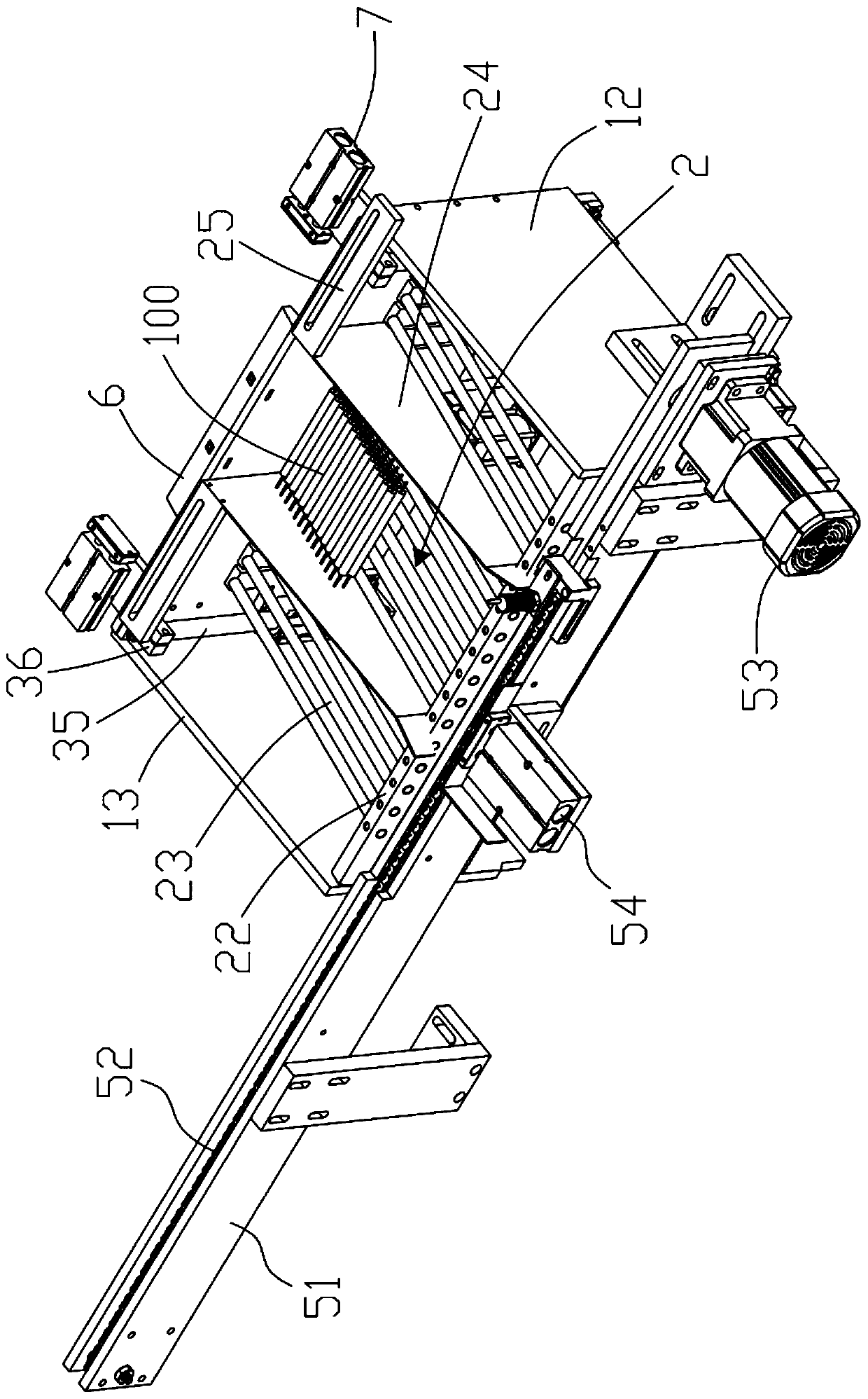
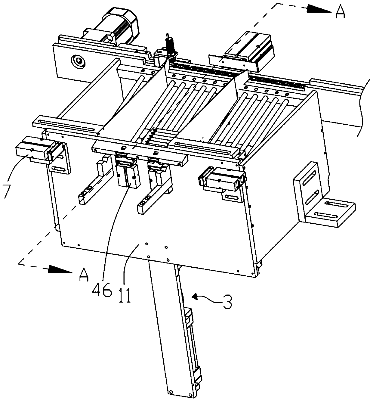
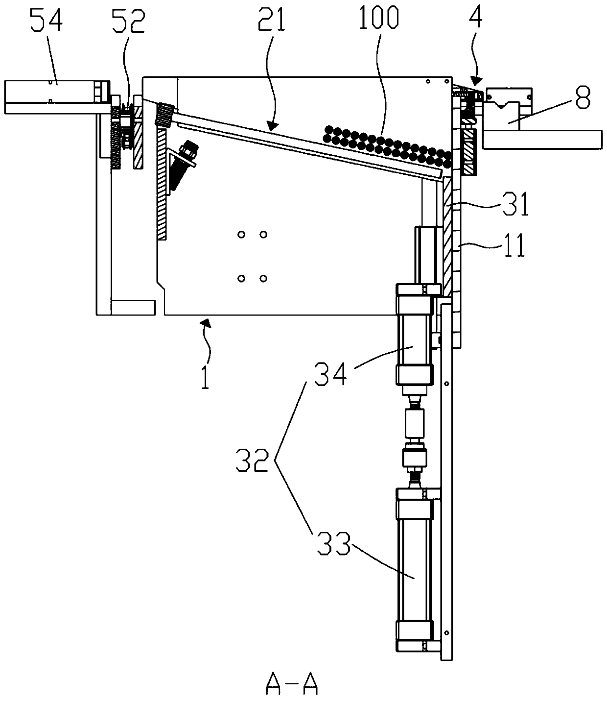
[0034] Such as Figure 1 to Figure 5 As shown, this embodiment provides a pipe loading device for use in electric heating pipe processing equipment, which includes a frame 1 and an electronic control module arranged on the frame 1, and also includes a material bin 2, a pipe jacking assembly 3 and a pusher tube assembly4. In an embodiment, the tube body 100 is a cylindrical structure. In other embodiments, the tube body 100 may also be a prism structure.

[0035] Wherein, the frame 1 of the present embodiment is in the shape of a cuboid, including a fir...


PUM


Abstract

The invention provides a pipe feeding device which comprises a rack, an electric control module, a storage bin, a pipe jacking assembly and a pipe pushing assembly. The pipe jacking assembly comprisesa lifting plate and a first power part; the first power part is arranged on a first side plate of the rack and connected with the lifting plate, and the lifting plate is driven to ascend and lifts pipe bodies provided at the storage bin; the pipe pushing assembly comprises a first pushing block and a second power part; a first side plate of the rack is provided with a through hole, and the through hole is higher than the stacking height of the pipe bodies; the first pushing block is inserted into the through hole; the second power part is in transmission connection with the first pushing block and drives the first pushing block to stretch and retract in the through hole; and during the lifting process of the lifting plate, when the distance between the lifting plate and the first pushingblock is larger than the outer diameter of one pipe body and smaller than the sum of the outer diameters of the two pipe bodies, the second power part drives the first pushing block to extend out fromthe through hole firstly and then retract. The device is compact and ingenious in structure, full-automatic pipe feeding is realized, the condition of excessive feeding is effectively avoided, and the production efficiency is greatly improved.

Description

technical field [0001] The invention relates to the field of electric heating tube processing, in particular to a tube upper device. Background technique [0002] Electric heating tube, also known as electric heating tube, is an electrical component that can convert electrical energy into heat energy. Electric heating tubes are installed in electric water heaters, electric kettles, and heating furnaces that are often used in daily life. [0003] Generally, electric heating tubes are composed of metal tubes, heating wires, insulating powders, seals and ceramic beads. Wherein, the heating wire is arranged in the metal tube. Insulating powder is filled inside the tube body. One end of the lead rod is connected with the heating wire, and the other end passes through the sealing member and protrudes out of the metal tube. This means that the manufacture of electric heating tubes must go through multiple processes. Therefore, metal tubes, semi-finished products of electric he...

Claims


Application Information

Patent Timeline
Patent Type & Authority Applications(China)
IPC IPC(8): B65G65/40B65G47/82B65G47/74
CPCB65G47/74B65G47/82B65G65/40B65G2201/0276
Inventor 杨雷刚
Owner 中山市雷通盛机械科技有限公司
Why Eureka
Try Eureka