Steel bar correction device for prefabricated column of prefabricated building

A correction device and prefabricated column technology, which is applied in the mechanical field, can solve the problems of column steel bar offset and unsatisfactory hoisting, and achieve the effect of fast detection and convenient use

Inactive Publication Date: 2020-05-19
锦萧建筑科技有限公司
View PDF6 Cites 1 Cited by
  • Summary
  • Abstract
  • Description
  • Claims
  • Application Information

AI Technical Summary

Problems solved by technology

[0004] Although the upper and lower floors are all prefabricated columns, due to the control of precision deviation in the production process and the transportation, storage, and hoisting of components, the installation of beam-column joints and the offset of column reinforcement during pouring cannot meet the requirements of hoisting

Method used


Image

  • Steel bar correction device for prefabricated column of prefabricated building
  • Steel bar correction device for prefabricated column of prefabricated building
  • Steel bar correction device for prefabricated column of prefabricated building

Examples


Embodiment Construction

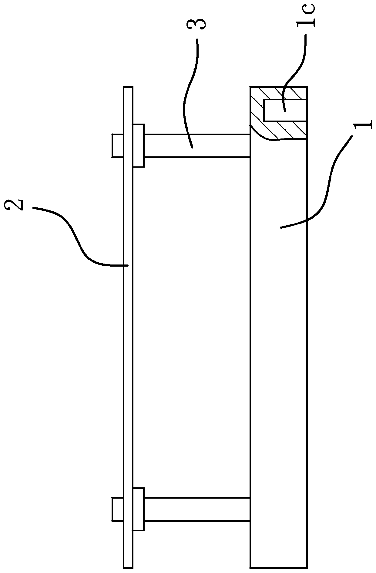
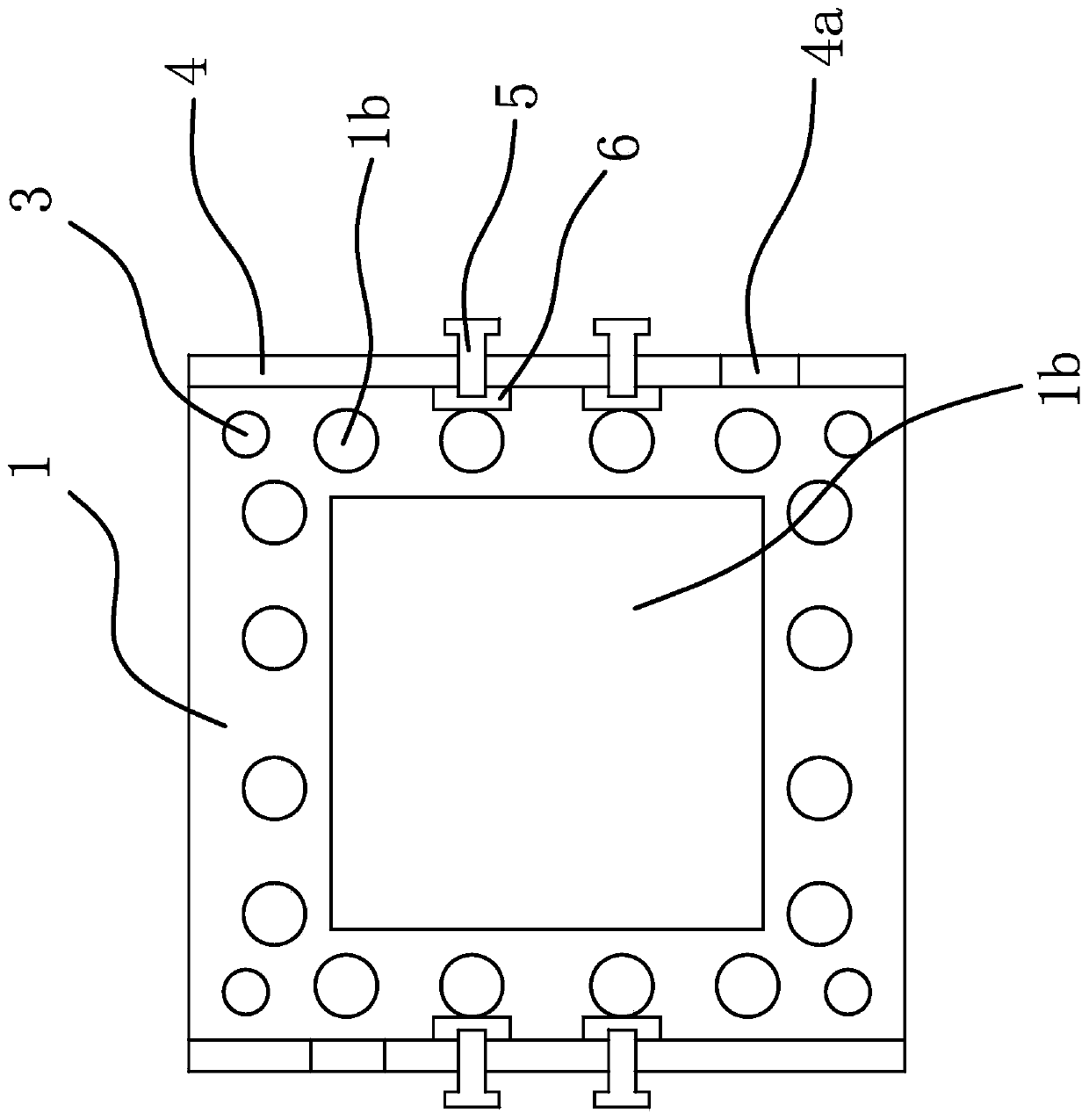
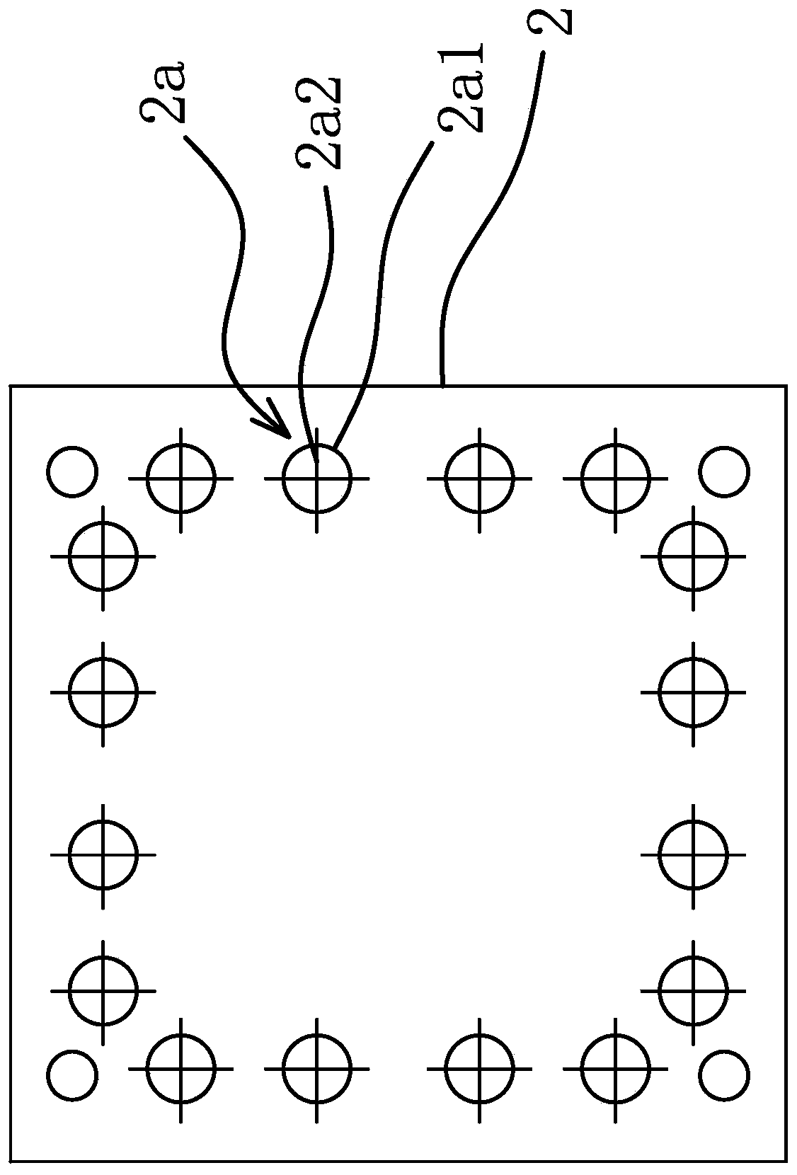
[0037] Such as figure 1 and figure 2 and image 3 As shown, the steel bar correction device of the prefabricated column of the prefabricated building includes a bottom plate 1, a correction plate 2 and a connecting rod 3, the lower end of the connecting rod 3 is connected to the bottom plate 1, and the upper end of the connecting rod 3 is connected to the correction plate 2, and the bottom plate 1 has a number of through calibration holes 1a close to its edge, the calibration plate 2 is a transparent material and has a number of calibration marks 2a on the calibration plate 2, and the calibration marks 2a are set in one-to-one correspondence with the calibration holes 1a.

[0038] The bottom plate 1 has a through hole 1b in the center, and the calibration holes 1c are distributed around the through hole 1b.

[0039] The edge of the bottom plate 1 is fixedly connected with a strip-shaped fixing strip 4, and the fixing strip 4 has a positioning structure. When the steel bar o...


PUM


Abstract

The invention provides a steel bar correction device for a prefabricated column of a prefabricated building, and belongs to the technical field of machinery. The steel bar correction device solves theproblem of poor stability in the prior art. The steel bar correction device for the prefabricated column of the prefabricated building comprises a bottom plate, a correction plate and a connecting rod, wherein the lower end of the connecting rod is connected to the bottom plate; the upper end of the connecting rod is connected to the correction plate; a plurality of through correction holes are formed in the bottom plate close to the edge of the bottom plate; the correction plate is made of a transparent material and is provided with a plurality of correction marks; and the correction marks and the correction holes are arranged in a one-to-one correspondence mode. The steel bar correction device for the prefabricated column of the prefabricated building is high in stability.

Description

technical field [0001] The invention belongs to the technical field of machinery, and relates to a steel bar correction device for an assembled building prefabricated column. Background technique [0002] The joints between the prefabricated lower columns and the upper columns of the prefabricated building are cast-in-place, and the joints are connected by sleeve grouting. [0003] It can be seen that the position of the reserved steel bars in the lower layer must correspond to the position of the grouting sleeve in the upper layer, and the accuracy requirements are high. Before hoisting the precast columns, it is required to ensure that the position adjustment of a single column bar does not exceed 2 mm error, and the overall column bar error of the entire node It must not exceed 5 mm, which is very difficult in construction practice. [0004] Although the upper and lower floors are all prefabricated columns, due to the control of precision deviation in the production proc...

Claims


Application Information

Patent Timeline
Patent Type & Authority Applications(China)
IPC IPC(8): E04G21/18
CPCE04G21/1841
Inventor 袁建生陈象倪志先李国昌谢锋丁宗安赵成芳戚洪亮陆春梁
Owner 锦萧建筑科技有限公司
Why Eureka
Try Eureka