Radar and infrared fused unmanned aerial vehicle landing control method and device

A control method and unmanned aerial vehicle technology, applied to ground devices, non-electric variable control, control/regulation systems, etc., can solve problems such as high cost, dangerous bombing, and inability to land, and achieve the effect of low cost

Inactive Publication Date: 2020-05-19
HUNAN NOVASKY ELECTRONICS TECH
View PDF14 Cites 6 Cited by
  • Summary
  • Abstract
  • Description
  • Claims
  • Application Information

AI Technical Summary

Problems solved by technology

[0003] At present, the course of the UAV depends on the compass, and it needs to rely on the GPS signal during take-off and landing. At about 2 meters to 3 meters, although the accuracy of differential GPS is high, the accuracy is at the centimeter level, but the cost is expensive, and the cost of a single module is very high, and to ensure GPS accuracy usually requires a relatively open space above the GPS module. When it is more complicated, such as flying in a group of buildings with many tall buildings, the distance between tall buildings is short, the GPS signal is usually poor and unstable, and the GPS coordinates are prone to drift, and GPS signals cannot even be obtained in some areas, so there is no When the man-machine relies on the GPS signal to land, it will lead to unstable flight during the landing process, or the landing position is inaccurate, and it cannot land after the GPS signal cannot be found. situation, it is impossible to ensure the stable and precise landing of the UAV

Method used


Image

  • Radar and infrared fused unmanned aerial vehicle landing control method and device
  • Radar and infrared fused unmanned aerial vehicle landing control method and device
  • Radar and infrared fused unmanned aerial vehicle landing control method and device

Examples


Embodiment Construction

[0040] The present invention will be further described below in conjunction with the accompanying drawings and specific preferred embodiments, but the protection scope of the present invention is not limited thereby.

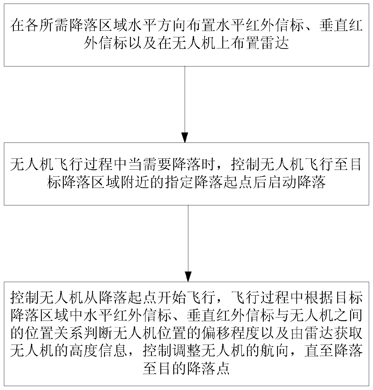
[0041] Such as figure 1 As shown, the steps of the UAV landing control method for radar and infrared fusion in this embodiment include:

[0042] S1. Arrange horizontal infrared beacons with vertical radiation directions in the horizontal direction of each required landing area, arrange vertical infrared beacons with horizontal radiation directions in the vertical direction, and arrange radars with ranging functions on UAVs;

[0043] S2. Landing start: when the UAV needs to land during the flight, control the UAV to fly to the designated landing starting point near the target landing area and then start the landing, and then go to step S3;

[0044] S3. Landing control: control the UAV to start flying from the landing point, and judge the degree of deviation of t...


PUM


Abstract

The invention discloses a radar and infrared fused unmanned aerial vehicle landing control method and device. The method comprises the steps that S1, horizontal infrared beacons and vertical infraredbeacons are arranged in all areas needing landing in the horizontal direction, and radars are arranged on an unmanned aerial vehicle; S2, when the unmanned aerial vehicle needs to land in the flight process, the unmanned aerial vehicle is controlled to fly to a designated landing starting point near the target landing area and then starts to land, and the step S3 is executed; S3, controlling the unmanned aerial vehicle to fly from the landing starting point, wherein in the flying process, the deviation degree of the position of the unmanned aerial vehicle is judged according to the position relation among the horizontal infrared beacons, the vertical infrared beacons and the unmanned aerial vehicle in the target landing area, and the height information of the unmanned aerial vehicle is obtained through radar; and controlling and adjusting the course of the unmanned aerial vehicle according to the deviation degree of the position of the unmanned aerial vehicle and the height informationof the unmanned aerial vehicle until landing to the target landing point. The method has the advantages of simple implementation method, low implementation cost, high control efficiency and precisionand the like.

Description

technical field [0001] The invention relates to the technical field of unmanned aerial vehicle control, in particular to a method and device for controlling unmanned aerial vehicle landing by radar and infrared fusion. Background technique [0002] UAVs can be used to perform various difficult and dangerous tasks, so they are gradually widely used in various fields, such as dangerous inspections in fires, high-altitude inspections of power cables, personnel searches in geological disasters, and dangerous situations. Inspection and delivery of drone cargo, etc. [0003] At present, the course of the UAV depends on the compass, and it needs to rely on the GPS signal during take-off and landing, especially during the landing process. In order to achieve accurate landing to the designated position, the GPS signal must be accurate, and the ordinary GPS positioning accuracy is generally low. At about 2 meters to 3 meters, although the accuracy of differential GPS is high, the acc...

Claims


Application Information

Patent Timeline
Patent Type & Authority Applications(China)
IPC IPC(8): G05D1/10B64F1/00
CPCB64F1/00G05D1/101
Inventor 李新祥周琪瑜郭浩
Owner HUNAN NOVASKY ELECTRONICS TECH
Why Eureka
Try Eureka