Embedded software interface case automatic generation method

An embedded software and interface technology, applied in the field of automatic generation of embedded software interface use cases, can solve problems such as unfavorable iterative incremental software development and testing, difficulty in ensuring the quality of test work, and difficulty in reusing test cases, and achieves the goal of facilitating development and The effect of testing, low testing cost and high testing efficiency

Active Publication Date: 2020-05-19
北京轩宇信息技术有限公司
View PDF7 Cites 3 Cited by
  • Summary
  • Abstract
  • Description
  • Claims
  • Application Information

AI Technical Summary

Problems solved by technology

[0004] (1) Low test efficiency and high test cost;
[0005] (2) Affected by the technical ability and knowledge reserve of the testers, it is difficult to guarantee the quality of the test work;
[0006] (3) Test cases are difficult to reuse, which is not conducive to iterative incremental software development and testing

Method used


Image

  • Embedded software interface case automatic generation method
  • Embedded software interface case automatic generation method
  • Embedded software interface case automatic generation method

Examples


Embodiment 1

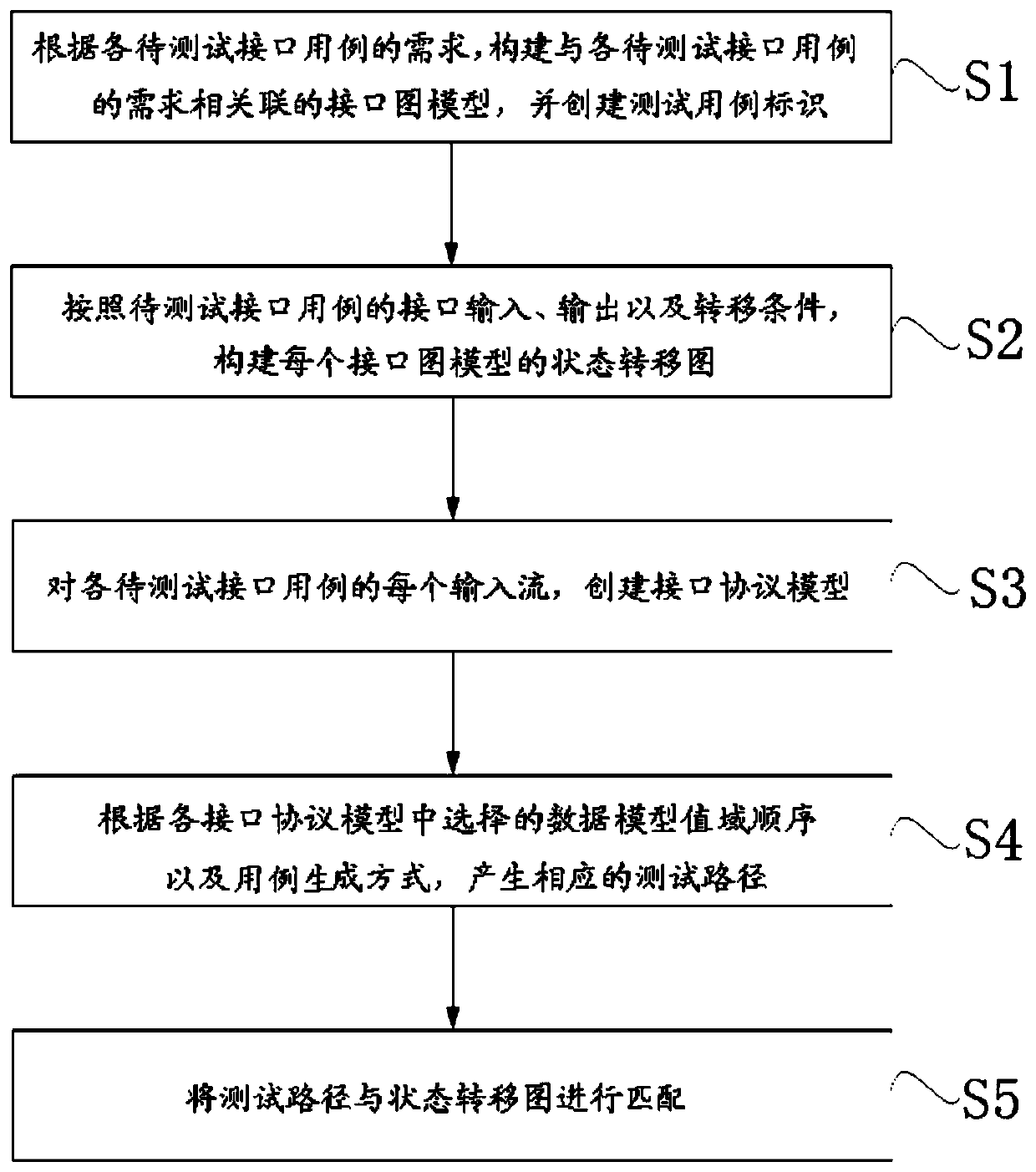
[0029] refer to figure 1 , shows a flow chart of steps of a method for automatically generating embedded software interface use cases in the present invention. In this embodiment, the method for automatically generating embedded software interface use cases includes:

[0030] Step S1, according to the requirements of each interface use case to be tested, construct an interface graph model associated with the requirements of each interface use case to be tested, and create a test case identifier; wherein, one interface use case to be tested corresponds to a unique test case identifier.

[0031] Step S2, constructing a state transition diagram of each interface diagram model according to the interface input, output and transition conditions of the interface use case to be tested.

[0032] Step S3, for each input flow of each interface use case to be tested, create an interface protocol model.

[0033] Preferably, the interface protocol model adopts an XML-based configurable me...

Embodiment 2

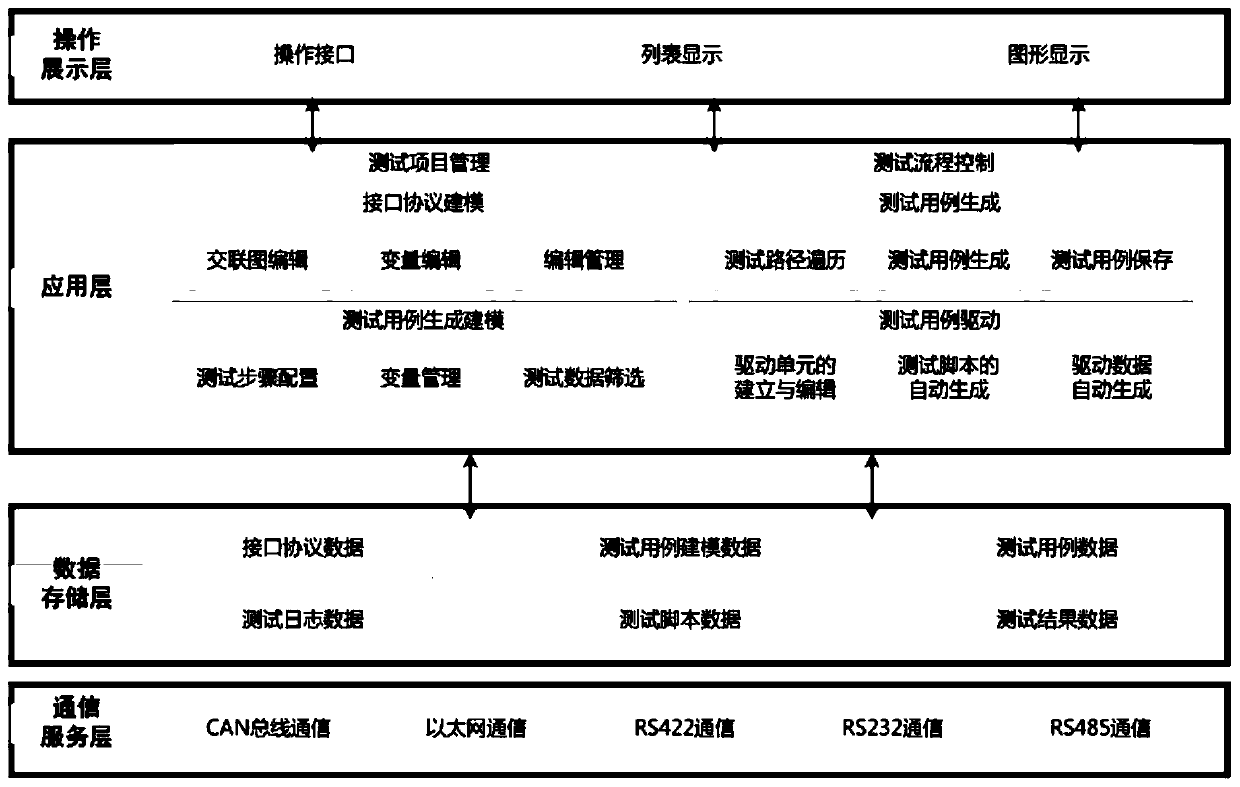
[0044] refer to figure 2, shows a system architecture diagram of the automatic generation of embedded software interface use cases in the present invention. The method for automatically generating embedded software interface use cases in the present invention is under the automatic test framework of MBT, and the process mainly focuses on the description of static characteristics of embedded software from building protocol models to generating test case collections. MBT automated testing framework is divided into "three levels, one process": test model layer, test case layer, physical storage layer and test management process. The core task of the test model layer is to construct the SUT interface protocol model. The core task of the test case layer is to generate test data, data path and test case collection. The core task of the physical storage layer is to provide physical storage services for the elements of the test model layer and test case layer, including the physica...


PUM


Abstract

The invention discloses an embedded software interface case automatic generation method. The method comprises the following steps: constructing an interface graph model associated with the requirementof each to-be-tested interface case according to the requirement of each to-be-tested interface case, and creating a test case identifier; constructing a state transition diagram of each interface diagram model according to the interface input, output and transition conditions of the to-be-tested interface case; creating an interface protocol model for each input stream of each to-be-tested interface case; generating a corresponding test path according to a data model value domain sequence selected in each interface protocol model and a use case generation mode; and matching the test paths with the state transition graphs to obtain matched keywords of the test paths in the corresponding state transition graphs, and performing data filling to complete instantiation of the to-be-tested interface cases. Automatic planning, generation, execution and evaluation of embedded software interface cases can be realized.

Description

technical field [0001] The invention relates to the technical field of embedded software testing, in particular to a method for automatically generating embedded software interface use cases. Background technique [0002] In embedded software testing, interface testing, as an important testing type, plays a very prominent role in software testing. Especially in the field of aerospace, there are many types of software interfaces and complex structures, and there are great differences in the interfaces of different types of software products, so it is difficult to describe them in formal language. More importantly, the requirements of high reliability and high coverage of embedded software mean that the types and quantities of test cases must be very large in order to fully and accurately cover various functions of the interface and ensure the security of the software. Therefore, efficient software testing is necessary, including automatic planning, generation, execution and ...

Claims


Application Information

Patent Timeline
Patent Type & Authority Applications(China)
IPC IPC(8): G06F11/36
CPCG06F11/3684G06F11/3688Y02D10/00
Inventor 虞砺琨于倩左万娟董燕陈华南郭华王小丽黄晨郑小萌
Owner 北京轩宇信息技术有限公司
Why Eureka
Try Eureka