
Cable trench support and cable trench using same

A cable trench and base technology, applied in the field of substations, can solve problems such as easy misalignment, and achieve the effect of flexible setting and preventing slippage

Inactive Publication Date: 2020-05-19
房淑贤
View PDF5 Cites 2 Cited by
  • Summary
  • Abstract
  • Description
  • Claims
  • Application Information

AI Technical Summary

Problems solved by technology

[0005] The purpose of the present invention is to solve the problem that the existing cable trench support is easy to dislocate and cause stacking and slipping, and provides a cable trench support and a cable trench using the support

Method used


Image

  • Cable trench support and cable trench using same
  • Cable trench support and cable trench using same
  • Cable trench support and cable trench using same

Examples


specific Embodiment approach 1

[0028] Specific implementation mode one: the following combination figure 1 , Figures 3 to 10 To illustrate this embodiment, the cable trench support 1 is an indispensable part in the cable trench, Figure 8 The shown cable trench support has no baffle at the end, so the cables are easy to fall off. Figure 9 There are baffles at the end of the cable trench support shown, but the flattened design itself is prone to the problem that the cables are misaligned and stacked. This kind of stacking phenomenon should be avoided by those skilled in the art during the cable laying process. Figure 10 The cable trench support shown has added multiple grooves, which can solve the problem of cable misalignment to a certain extent, but because the size of the groove has been solidified, the number of cables that can be laid on the cable trench support is limited by the number of grooves. If the cable When the diameter is significantly smaller than the size of the groove, the limited spac...

specific Embodiment approach 2

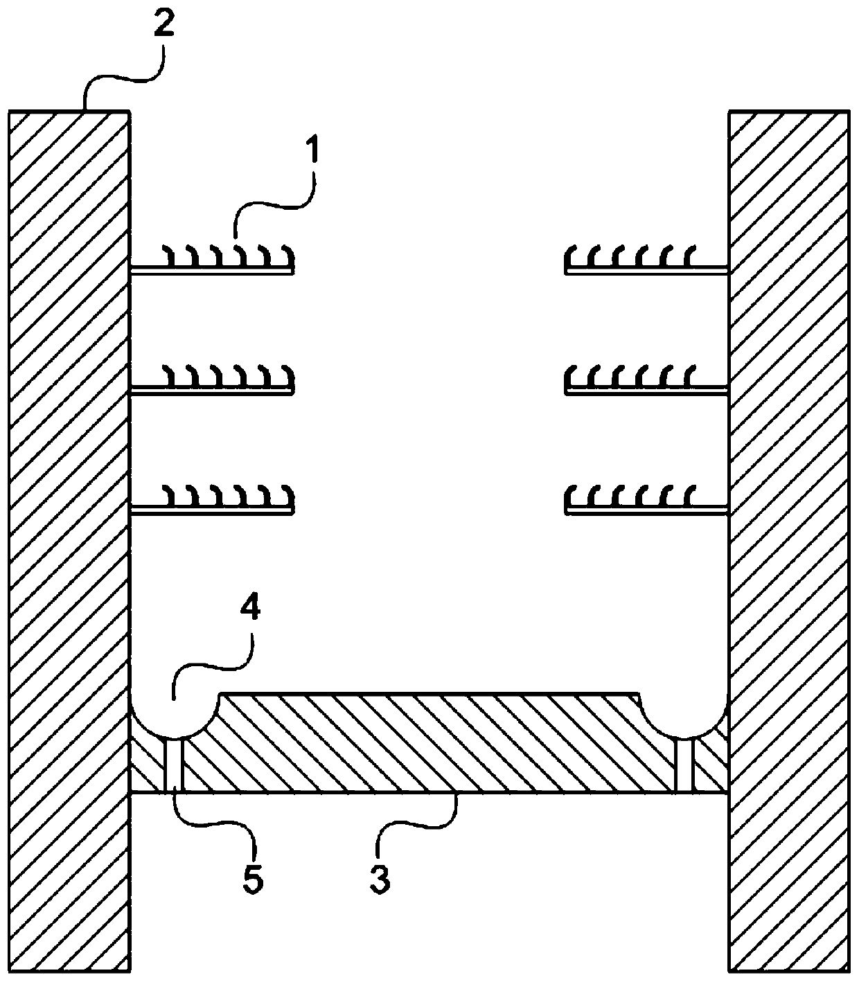
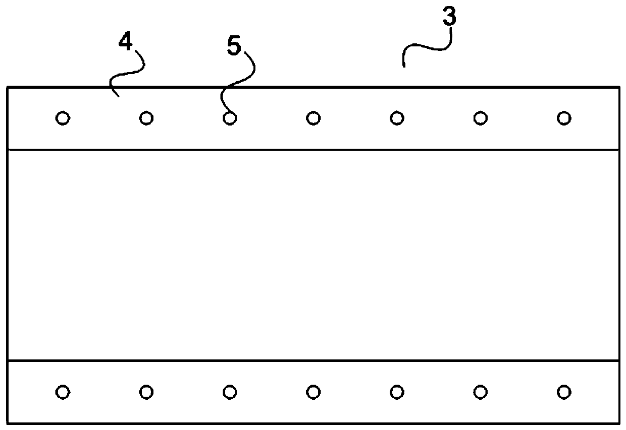
[0041] Specific implementation mode two: the following combination figure 1 and figure 2Describe this embodiment, the cable trench described in this embodiment includes a side plate 2, a bottom plate 3 and a plurality of cable trench supports 1, two side plates 2 and a bottom plate 3 form an H-shaped structure, and the distance between the bottom plate 3 and the bottom end of the side plate 2 is 100mm to 200mm; one groove 4 is arranged on the upper surface of the bottom plate 3 close to the side plate 2, and the groove 4 is arranged along the direction of the cable trench, and drainage through holes 5 are uniformly distributed along the direction of the cable trench at the bottom of the groove;

[0042] The cable trench support 1 is the cable trench support according to claims 1-5.

[0043] The groove 4 is a square groove or a semicircular groove. figure 1 Examples of semicircular grooves given in .

[0044] In the actual application process, it is inevitable that rainwa...


PUM


Abstract

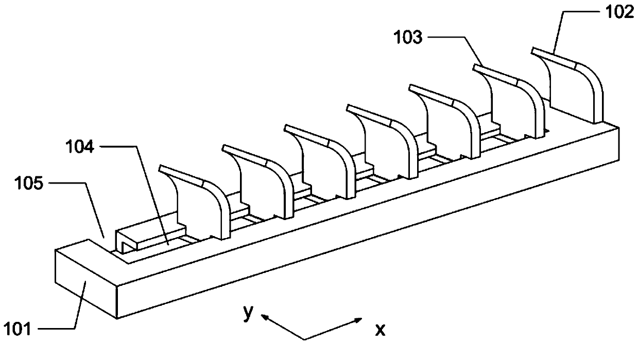
The invention discloses a cable trench support and a cable trench using the same, belongs to the field of substations, and aims to solve the problem that an existing cable trench support is prone to dislocation, stacking and slipping. The cable trench support comprises a base, an end limiting plate and a plurality of movable arc-shaped limiting plates. The base is of a long-strip-plate-shaped structure, the end limiting plate is fixedly arranged on the upper surface of the end of the base, an inverted-T-shaped groove is formed in the upper surface of the base in the length x direction, and theinverted-T-shaped groove is provided with a moving-in notch in the tail portion of the base. The movable arc-shaped limiting plate comprises an arc-shaped baffle and a sliding base, wherein the bottom of the arc-shaped baffle is fixed to the sliding base, and the two sides of the bottom of the arc-shaped baffle are each provided with a clamping notch; and the sliding base moves into the inverted-T-shaped groove from the moving-in notch, in the tail portion of the base, of the inverted-T-shaped groove and drives the arc-shaped baffle to slide in the length x direction of the base. According tothe invention, cables can be arranged as many as possible while the cables are prevented from slipping and being stacked.

Description

technical field [0001] The invention belongs to the field of substations and relates to a support structure of a cable trench. Background technique [0002] As the core link of the power system, the substation is responsible for the high and low voltage conversion and power supply tasks in the area. Cables are usually laid centrally in cable trenches in substations. Cable trench is an underground pipeline for laying and replacing electric power or telecommunication cable facilities, and it is also an enclosure structure for laying cable facilities. Cable trenches, ground cable trenches and underground cable trenches are commonly used in power transformation projects. [0003] Due to the large number of secondary cables in the cable trench and their different uses, they can usually be divided into AC secondary cables, DC secondary cables, etc. according to different voltage categories, and can be divided into control cables and signal cables according to different functions....

Claims


Application Information

Patent Timeline
Patent Type & Authority Applications(China)
IPC IPC(8): H02G9/02
CPCH02G9/02
Inventor 刘发刚孙玉君杜忠秋岳立国郭士昌房淑贤张继梅杨吉英王明佳刘东旭高原孙毓张振龙
Owner 房淑贤
Learn More