Vernier type high-precision welding fixture and measuring tool with seat

A welding fixture, high-precision technology, applied in the direction of auxiliary devices, manufacturing tools, welding equipment, etc., can solve the problem that the welding plate or welding fixture or marking line cannot meet the requirements of frequent changes in technical status, and achieve easy use , the effect of quantitative measures of economic

Active Publication Date: 2014-07-16
内蒙古第一机械集团股份有限公司
View PDF0 Cites 0 Cited by
  • Summary
  • Abstract
  • Description
  • Claims
  • Application Information

AI Technical Summary

Problems solved by technology

[0011] a. Solve the requirement that the welding plate or welding jig or marking line cannot meet the frequent changes of th

Method used


Image

  • Vernier type high-precision welding fixture and measuring tool with seat
  • Vernier type high-precision welding fixture and measuring tool with seat
  • Vernier type high-precision welding fixture and measuring tool with seat

Examples


Embodiment 1

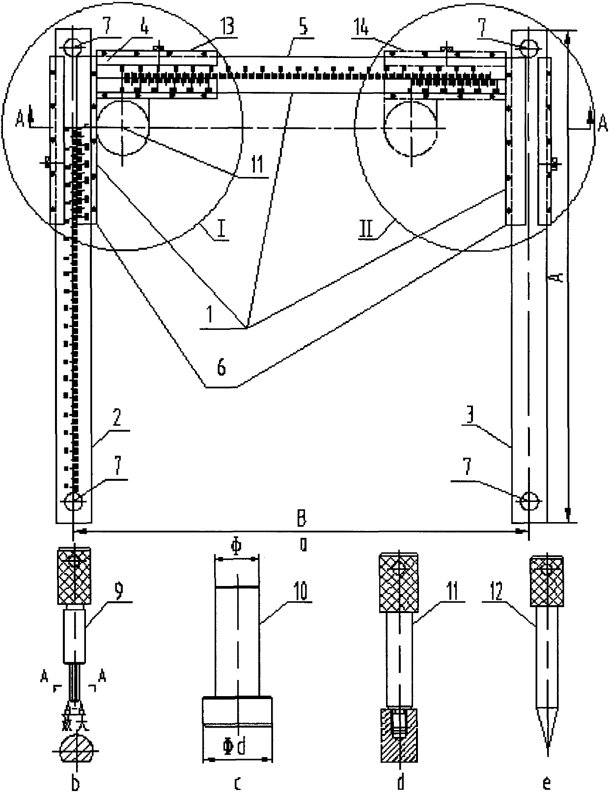
[0056] Such as Figure 12 As shown, on a certain welding plane, there are 25 auxiliary seats evenly distributed on the indexing circle based on the center of the hole ФD and there are position requirements. The implementation steps are as follows:

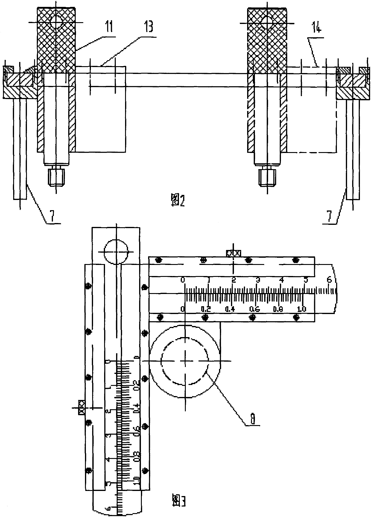
[0057] (1) Adjust the position of the fixture so that the overall beam ruler 1 is parallel to the horizontal centerline of the reference hole ФD, and the longitudinal beam ruler 2 and longitudinal beam 3 are parallel to the vertical centerline of the reference hole ФD at the same time. When the location hole 8 is at the starting position, the center position of 13 is the coordinate origin, and its horizontal centerline is the horizontal axis, and the vertical centerline is the vertical axis, and a plane Cartesian coordinate system is established, so that the location pin 11, the location pin 9, the location mandrel 10 or datum positioning pin 12 can reach any point in the plane Cartesian coordinate system of fixture itself.

[00...

Embodiment 2

[0066] Such as Figure 13 As shown, on a certain welding plane, there are 36 attachments that are evenly distributed. They not only have positional requirements relative to reference plane A and reference plane B, but also have positional requirements between two adjacent attachments. The implementation steps are as follows:

[0067] (1) Take the intersection of datum plane A and datum plane B as the coordinate origin, the horizontal direction as the horizontal axis, and the vertical direction as the vertical axis to establish a plane Cartesian coordinate system.

[0068] (2) Convert the positional dimensions between two pairs of 36 attached seats into plane Cartesian coordinates and record them.

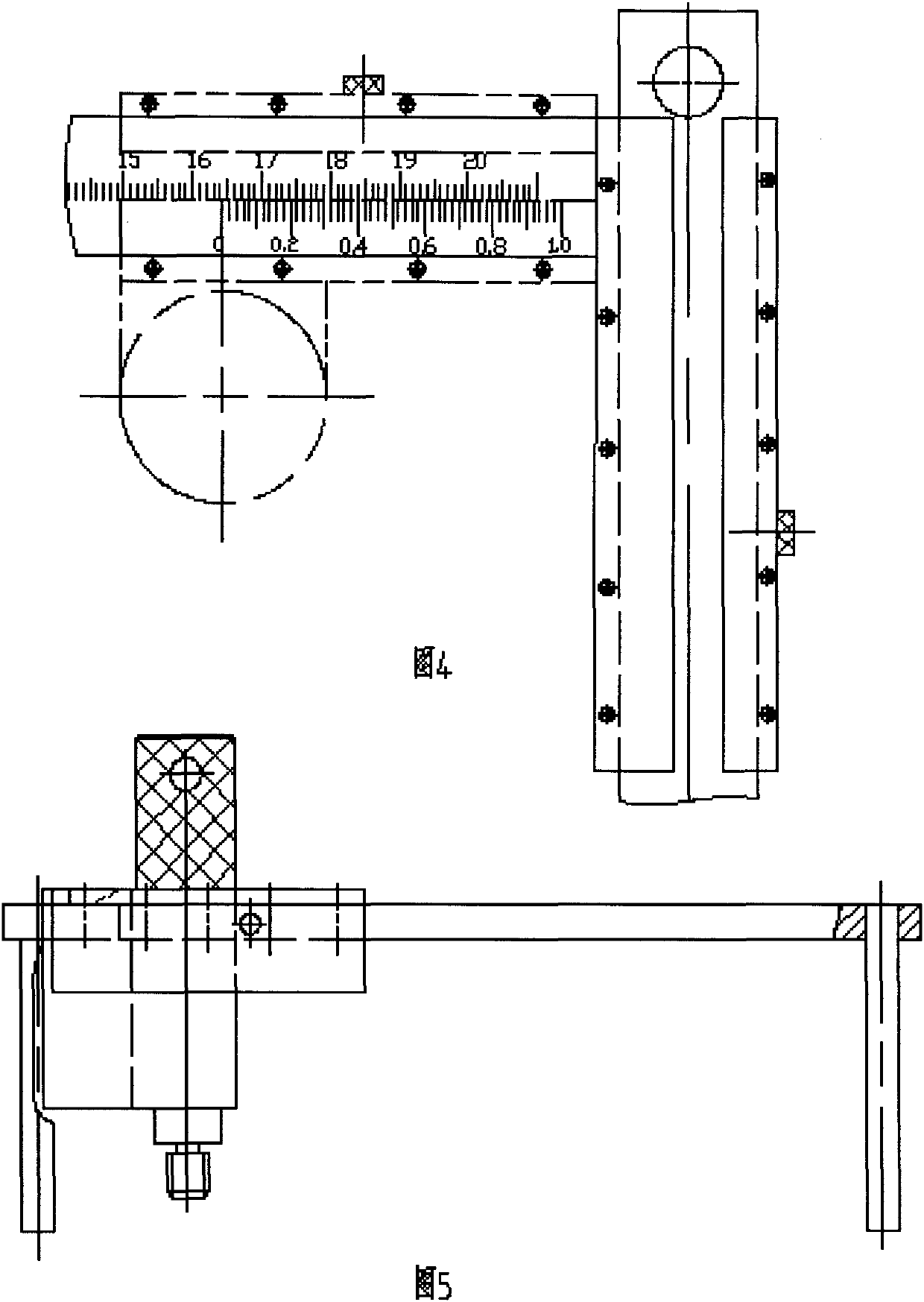
[0069] (3) After passing the reference positioning pin 12 through the positioning hole 8 on the vernier ruler 4 from top to bottom (the matching relationship is H7 / g6), by sliding the vernier ruler 4 and the overall beam ruler 1 at the same time, the position of the reference posit...


PUM


Abstract

The invention relates to a vernier type high-precision attachment welding fixture and a measuring tool, which are used for assembly welding and quantitative detection of various attachments on armored vehicles. Solved the problems of welding and quantitative measurement of the attached seat of the scientific research and trial production vehicle. It consists of a magnetic bar, a longitudinal beam ruler, a longitudinal beam, an integral beam ruler, a vernier ruler, a positioning pin, a positioning pin and a positioning mandrel or a reference positioning pin. It is a longitudinal ruler perpendicular to the horizontal ruler, the longitudinal ruler at one end has a scale, the longitudinal beam ruler, the longitudinal beam is perpendicular to the horizontal ruler of the overall beam ruler, the longitudinal beam ruler has a scale, and forms a vernier caliper structure with the vertical ruler with scale, The vernier scale swims on the horizontal scale of the overall beam scale to form a vernier caliper structure, and the vernier scale has a positioning hole. The invention is easy to use, satisfies the requirement of frequent change of assembly and welding technical states of various seat attachments on the scientific research and trial-manufacture vehicle, and can realize economical quantitative measurement at the same time.

Description

technical field [0001] The invention relates to a welding jig and measuring tool with a seat, in particular to a vernier type high-precision welding fixture and a measuring tool with a seat, which is used for the assembly and welding of various seats on armored vehicles and is randomly distributed on the same plane. Quantitative detection of the position of multiple holes or threaded holes. Background technique [0002] 1. Compared with the technical scheme of installing the welding attachment with the vernier type high-precision attachment welding jig, the existing technical solution for installing the welding attachment mainly has the following two points: [0003] (1) For scientific research and trial production vehicles with an output of one or several units, if the welding plate or welding fixture is designed to ensure the welding accuracy of the attached seat, their superiority in mass production cannot be obtained in trial production fully use. Because the manufactu...

Claims


Application Information

Patent Timeline
IPC IPC(8): B23K37/04
Inventor 张恩南
Owner 内蒙古第一机械集团股份有限公司
Why Eureka
Try Eureka