Office chair with cervical vertebra massage function

An office chair and functional technology, applied in the field of cervical spine massage, can solve the problems of inability to adjust, the angle of the massage device is fixed, etc., and achieve the effects of convenient storage and simple operation.

Active Publication Date: 2020-05-22
北京世纪京美家具(淮北)有限责任公司
View PDF2 Cites 3 Cited by
  • Summary
  • Abstract
  • Description
  • Claims
  • Application Information

AI Technical Summary

Problems solved by technology

[0004] The purpose of the present invention is to solve the shortcomings of the existing massage device, which has a fixed angle and cannot be adjusted, and proposes an office chair with cervical spine massage function.

Method used


Image

  • Office chair with cervical vertebra massage function
  • Office chair with cervical vertebra massage function
  • Office chair with cervical vertebra massage function

Examples


Embodiment 1

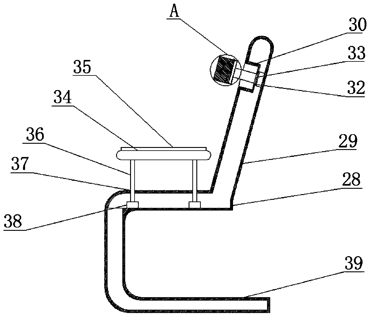
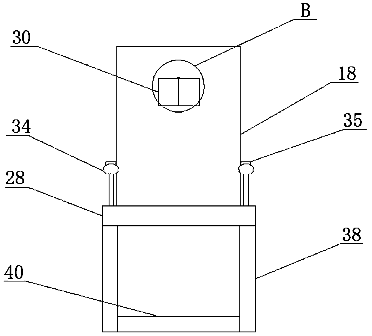
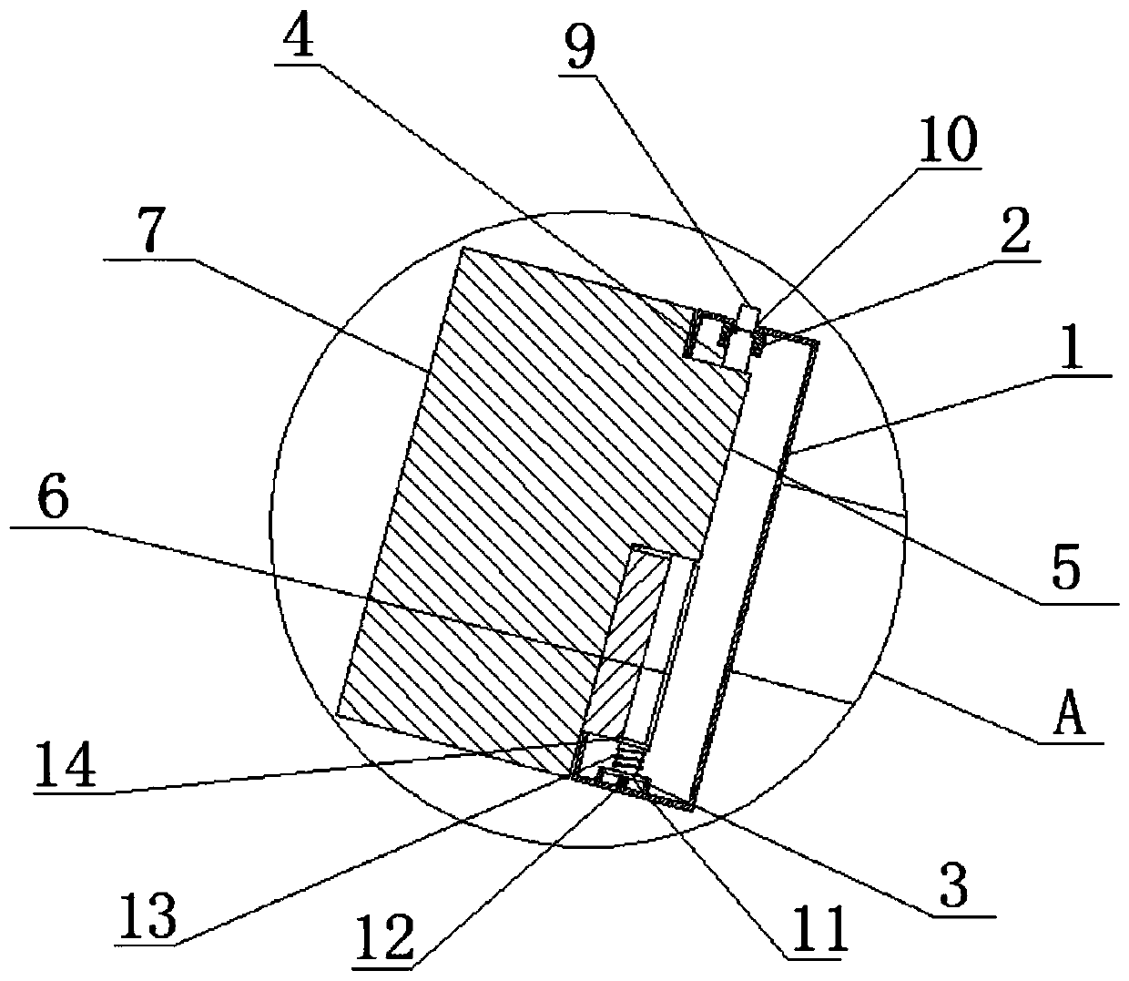
[0029] refer to Figure 1-5 , an office chair with cervical spine massage function, comprising a base box 1 and an office chair body 28, the top inner wall of the base box 1 is fixedly provided with a first card slot 2, and the bottom inner wall of the base box 1 is fixedly provided with a second card slot Slot 3, a central shaft 4 is slidably connected to the first card slot 2, a first massage board 5 and a second massage board 6 are rotatably connected to the central shaft 4, a first massage pillow 7 is fixedly connected to the first massage board 5, The second massage board 6 is fixedly connected with a second massage pillow 8, and the base box 1, the first massage board 5, the second massage board 6, the first massage pillow 7 and the second massage pillow 8 jointly form a massage structure;

[0030] One end of the central shaft 4 is fixedly connected with a button 9, the top of the base box 1 is provided with a first card hole 10, the button 9 is slidably connected to the...

Embodiment 2

[0042] refer to Figure 1-5 , an office chair with cervical spine massage function, comprising a base box 1 and an office chair body 28, the top inner wall of the base box 1 is fixedly welded with a first card slot 2, and the bottom inner wall of the base box 1 is fixedly welded with a second card slot Slot 3, the first card slot 2 is slidingly connected with a central shaft 4, the central shaft 4 is rotatably connected with a first massage board 5 and a second massage board 6, the first massage board 5 is fixedly welded with a first massage pillow 7, The second massage board 6 is fixedly welded with a second massage pillow 8, and the base box 1, the first massage board 5, the second massage board 6, the first massage pillow 7 and the second massage pillow 8 jointly form a massage structure;

[0043] One end of the central axis 4 is fixedly welded with a button 9, and the top of the base box 1 is provided with a first card hole 10, the button 9 is slidably connected to the inn...


PUM


Abstract

The invention belongs to the technical field of cervical vertebra massage, in particular to an office chair with a cervical massage function. Aiming at the problem that the angle of an existing massage device is fixed and can not be adjusted, the office chair of the scheme comprises a base box and an office chair body, a first clamping groove is fixedly formed on the inner wall of the top of the base box, and a second clamping groove is fixedly formed on the inner wall of the bottom of the base box. A center shaft is slidably connected into the first clamping groove, a first massage plate anda second massage plate are rotationally connected to the central shaft, a first massage pillow is fixedly connected to the first massage plate, and a second massage pillow is fixedly connected to thesecond massage plate. According to the present invention, the first massage block and the second massage block are rotationally arranged on the center shaft, and the center shaft, the limiting plate and the first spring are extruded through the buttons, so that the potential energy of a second spring is reduced, the purpose of easily rotating the first massage plate and the second massage plate toadjust the angle is achieved, and the operation is easy.

Description

technical field [0001] The invention relates to the technical field of cervical spine massage, in particular to an office chair with a cervical spine massage function. Background technique [0002] In daily office work, office chairs are indispensable. There are many types of office chairs, among which there are many multifunctional office chairs with various massage devices. Because they may maintain a posture for a long time at work, if things go on like this, it may cause cervical spine problems. . [0003] The application number is 201920017029.9, which discloses an office chair with cervical spine massage function, including a seat, a mounting frame and a massager box. The upper part of the seat is fixedly connected with a connecting column, and the upper end of the connecting column is fixedly connected with a mounting frame. There is a driving motor inside the device box, and the output end of the driving motor is keyed to a rotating shaft, and the other end of the r...

Claims


Application Information

Patent Timeline
Patent Type & Authority Applications(China)
IPC IPC(8): A47C7/38A61H1/00
CPCA47C7/38A61H1/008A61H2205/04A61H2201/0149
Inventor 张玉飞李健汤建设
Owner 北京世纪京美家具(淮北)有限责任公司
Why Eureka
Try Eureka