Mounting method of large storage tank floating tray guide pipe flexible sealing device

A technology for flexible sealing and large storage tanks, applied in protection devices, large containers, packaging, etc., can solve problems such as oil and gas leakage, and achieve the effect of eliminating static electricity accumulation

Inactive Publication Date: 2020-05-22
CHINA PETROLEUM & CHEM CORP +1
View PDF10 Cites 0 Cited by
  • Summary
  • Abstract
  • Description
  • Claims
  • Application Information

AI Technical Summary

Problems solved by technology

[0006] The purpose of the present invention is to propose a method for installing a flexible sealing device for the floating plate guide pipe of a large storage tank, so as to solve the problem of oil and gas leakage on the guide pipe of the floating roof of the large storage tank in the prior art

Method used


Image

  • Mounting method of large storage tank floating tray guide pipe flexible sealing device
  • Mounting method of large storage tank floating tray guide pipe flexible sealing device
  • Mounting method of large storage tank floating tray guide pipe flexible sealing device

Examples


Embodiment 1

[0040] Embodiment 1 of the present invention describes a flexible sealing device for a floating plate guide pipe of a large storage tank.

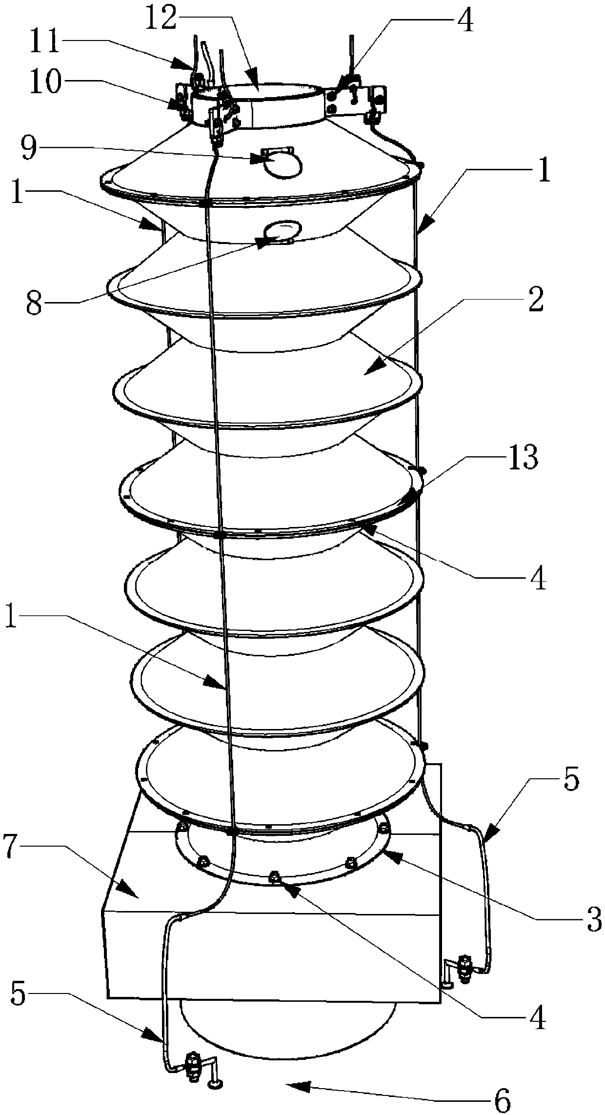
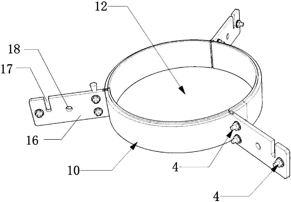
[0041] Such as figure 1 As shown, the flexible sealing device for the guide tube of the floating plate of the large storage tank includes a base 7, a flexible sealing tube 2, a sealing ring 10 and other components. in:

[0042] The base 7 is installed on the position above the floating plate 6 where the guide tube 12 passes, and surrounds the perforation on the guide tube 12 .

[0043] Preferably, the installation method of the base 7 can be welded connection, for example.

[0044] A through hole (not shown) through which the guide tube 12 passes upward is provided on the top of the base 7 .

[0045] The flexible sealing tube 2 is set on the guide tube 12 . in:

[0046] The bottom of the flexible sealing tube 2 is fixed on the base, and the fixing method is, for example:

[0047] A first reinforcement ring 3 is provided at the bottom...

Embodiment 2

[0057] This embodiment 2 also refers to a flexible sealing device for the guide pipe of the floating plate of a large storage tank. The flexible sealing device is different from the above-mentioned embodiment 1 in the following technical features, and other technical features can refer to the above-mentioned embodiment 1.

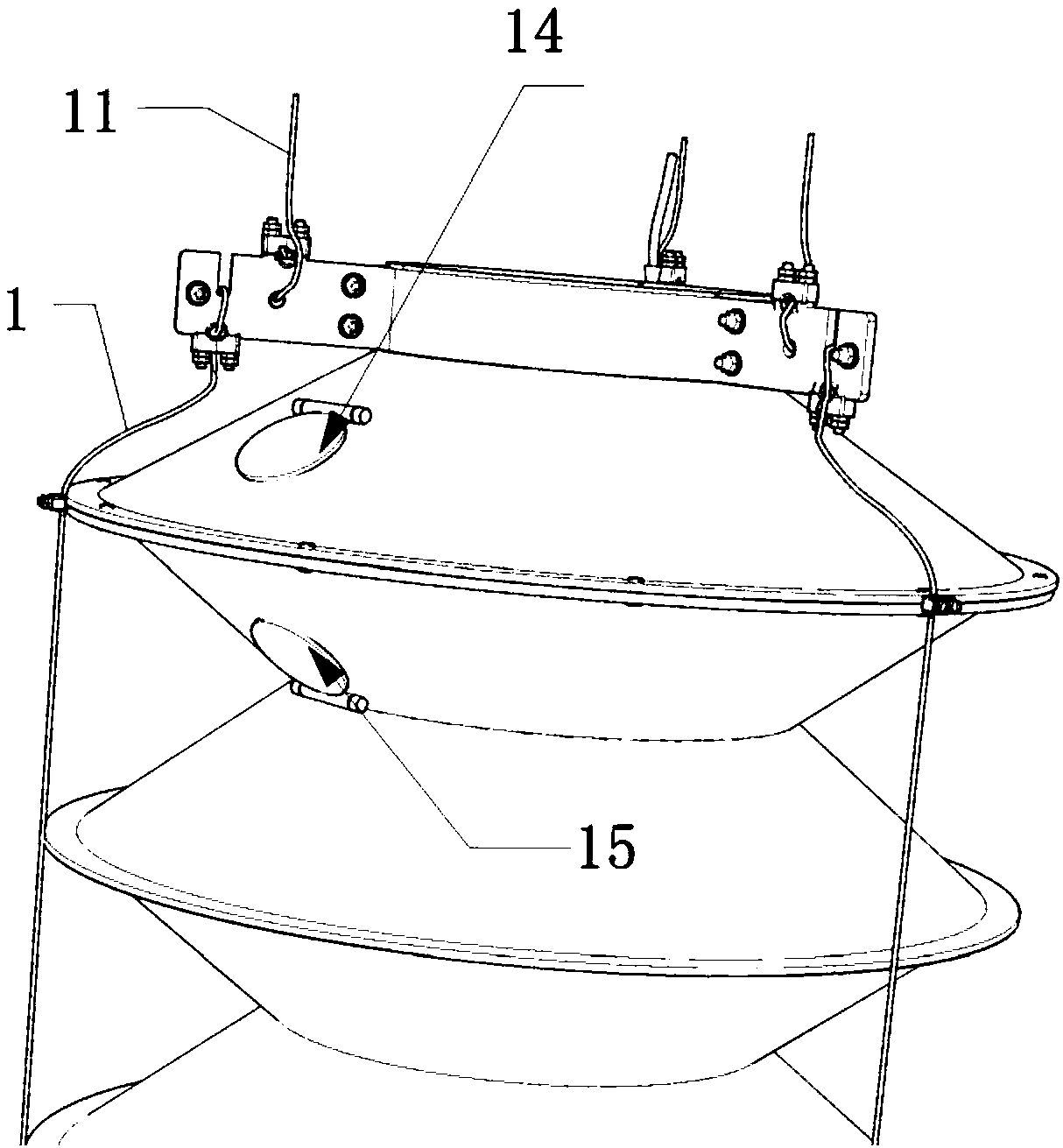
[0058] The top of the flexible sealing tube 2 in Embodiment 2 is provided with an outer self-closing hole 9 and an inner self-closing hole 8 .

[0059] When the pressure in the flexible sealing tube 2 increases to the first set threshold, the outer self-closing hole 9 exhales, and the inner self-closing hole 8 is sealed; when the pressure in the flexible sealing tube 2 decreases to the second setting threshold, The inner self-closing hole 8 sucks air, and the outer self-closing hole 9 is airtight.

[0060] Through the above-mentioned outer self-closing hole 9 and inner self-closing hole 8, the pressure adjustment can be automatically realized when the press...

Embodiment 3

[0070] This embodiment 3 also describes a flexible sealing device for the guide pipe of the floating plate of a large storage tank. Except for the following technical features that are different from the above-mentioned embodiment 2, other technical features of the flexible sealing device can refer to the above-mentioned embodiment 2.

[0071] A second reinforcing ring 13 is arranged on the flexible sealing tube 2 at intervals from top to bottom.

[0072] The second reinforcing ring 13 is connected with the flexible sealing tube 2 (for example, connected with bolts 4 ).

[0073] The flexible sealing device also includes several reinforcing ropes 1 .

[0074] Wherein, the top of the reinforcing rope 1 is fixed on the sealing ring 10 , and the bottom of the reinforcing rope 1 is connected with the floating disc 6 .

[0075] The circumference of each second reinforcing ring 13 is respectively provided with several U-shaped slots (not shown) for fixing the reinforcing rope.

[0...


PUM


Abstract

The invention discloses a mounting method of a large storage tank floating tray guide pipe flexible sealing device. The large storage tank floating tray guide pipe flexible sealing device comprises abase, a flexible sealing pipe and a flexible fixing ring. The mounting method includes the following steps that s1, the base is mounted at the position where a guide pipe above a floating tray penetrates through, and surrounds a penetrating hole in the guide pipe; s2, the flexible sealing pipe sleeves the guide pipe; and s3, the bottom of the flexible sealing pipe is fixed to the base, and the topof the flexible sealing pipe is mounted on the top of the guide pipe through the sealing fixing ring. The problem of oil and gas leakage on the large storage tank floating tray guide pipe is effectively solved.

Description

technical field [0001] The invention belongs to the field of oil and gas storage and transportation, and relates to a method for installing a flexible sealing device for a floating disk guide pipe of a large storage tank. Background technique [0002] The floating plate of the large storage tank is close to the edge, and there are two vertical steel pipes (guide pipes) on both symmetrical sides. The bottom end of the steel pipe is fixed on the bottom plate of the tank, and the top is fixed on the top of the tank wall. through vertically. [0003] In addition to being used for installing detection instruments and manual gauges, the guide pipe is used to control the movement of the pontoon and prevent the pontoon from capsizing or rotating. In addition, a certain number of small circular holes are evenly distributed on the guide tube. The purpose of opening the hole is to ensure the balance of the pressure difference between the inside and outside of the dipstick, otherwise ...

Claims


Application Information

Patent Timeline
IPC IPC(8): B65D88/34B65D88/42B65D90/24B23P21/00
CPCB23P21/00B65D88/34B65D88/42B65D90/24
Inventor 张玉平刘全桢管孝瑞陶彬马开良程庆利蒋秀
Owner CHINA PETROLEUM & CHEM CORP
Why Eureka
Try Eureka