Seabed natural gas hydrate collecting device

A collection device and natural gas technology, which is applied in the direction of mining fluid, earthwork drilling, wellbore/well components, etc., to achieve the effects of reliable connection, ensuring production safety, and convenient, fast and reliable control

Active Publication Date: 2016-07-20
SOUTHWEST PETROLEUM UNIV
View PDF3 Cites 16 Cited by
  • Summary
  • Abstract
  • Description
  • Claims
  • Application Information

AI Technical Summary

Problems solved by technology

[0006] The purpose of the present invention is to provide a seabed natural gas hydrate collection device for the above-mentioned problems, which mainly solves the problem of natural gas hydrate in the seabed mud bed, and does not form the escape of natural gas during the process of decomposing, collecting and exploiting and leakage problems, the present invention breaks through the conventional thinking mode, cleverly uses pressure regulation to form negative pressure and temp

Method used


Image

  • Seabed natural gas hydrate collecting device
  • Seabed natural gas hydrate collecting device
  • Seabed natural gas hydrate collecting device

Examples


Embodiment 1

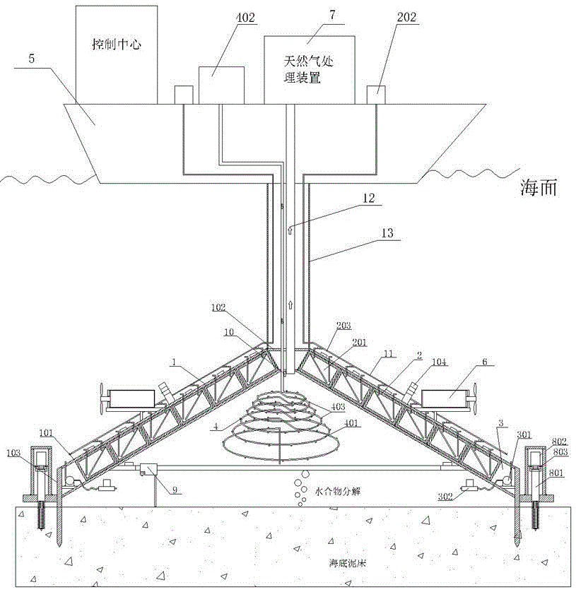
[0062] Such as figure 1 and Figure 13 As shown, the seabed natural gas hydrate collection device of the present invention includes a mother ship 5 and an empty natural gas collection cover 1. The mother ship 5 is provided with a natural gas collection and storage device 7 and a pressure supply module 202. The natural gas storage and storage device 7 The top of the natural gas collection cover 1 is connected to the top of the natural gas collection cover 1 through the gas production pipeline 12, and the natural gas collection cover 1 is connected to the bottom of the mother ship 5 through the riser 13, and the gas production pipeline 12 is arranged in the water riser 13; the bottom of the natural gas collection cover 1 is arranged around There is an anchoring system 8, a pressure regulation system 3 is provided at the bottom of the natural gas collection cover 1, a temperature regulation system 4 and an agitation system 9 are provided inside the natural gas collection cover 1...

Embodiment 2

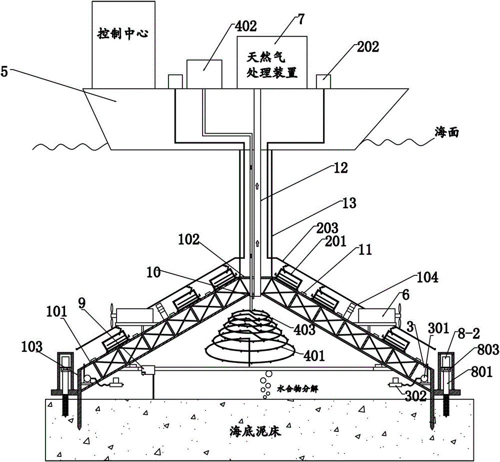
[0071] Such as figure 2 and Figure 14 As shown, this embodiment is similar to Embodiment 1, the difference is that: the outer wall of the natural gas collection cover 1 is provided with a density adjustment system 2, and the density adjustment system 2 includes a buoyancy module 201, a pressure supply module 202 and Pneumatic pipeline 203; wherein several buoyancy modules 201 are arranged on the outer wall of the housing 101, the buoyancy modules 201 include a sealed inner hollow box, an electronic liquid level gauge 207 is arranged in the box, and an electronic liquid level gauge 207 is arranged on the box There are drainage pipes 206 and air intake pipes 205 that communicate with the inside and outside, and the air intake pipes 205 of all buoyancy modules 201 are connected in parallel to the air pressure pipeline 203 , and the air pressure pipeline 203 is fixed on the outer wall of the shell 101 and passes through the riser 13 Connect to the pressure supply module 202.

...

Embodiment 3

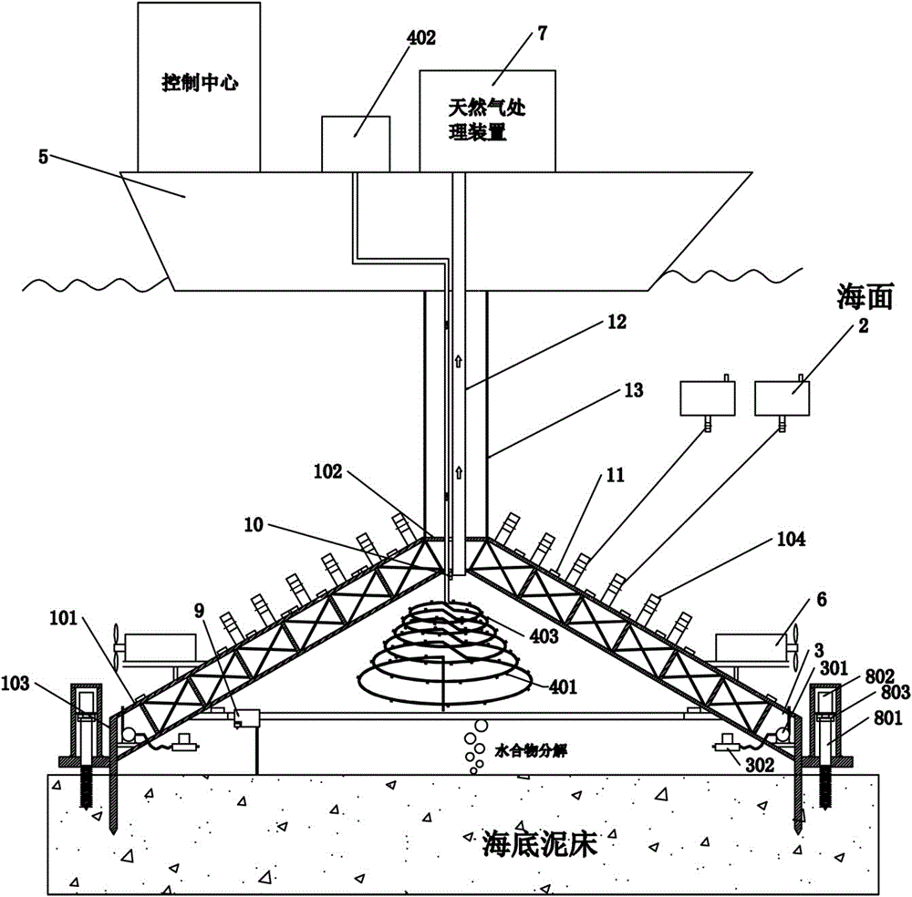
[0075] Such as image 3 and Figure 15 As shown, this embodiment is similar to Embodiment 1, and the difference is that a number of suspension rings 104 are arranged outside the natural gas collection cover 1, and a density adjustment system 2 is connected to the suspension rings 104 through cables. The system 2 includes several buoyancy modules 201 located outside the natural gas collection cover 1, the buoyancy modules 201 are sealed inner hollow boxes, the bottom of the buoyancy modules 201 is provided with a hanging ring, and the hanging ring and the hanging ring 104 pass through Cable connection, the top of the buoyancy module 201 is provided with a drainage pipe 204 connecting the inside and outside of the buoyancy module 201, the inside of the buoyancy module 201 is provided with an airbag 203, and the airbag 203 is connected to the air compressor 202 which can be controlled remotely and wirelessly.

[0076] Wherein the temperature regulation system 4 includes an oxyge...


PUM


Abstract

The invention discloses a seabed natural gas collecting device for suspension buoyancy tank electric heating, and belongs to the technical field of natural gas collection. The device comprises a mother ship and a hollowed natural gas collecting cover; a natural gas storage device is arranged on the mother ship, and is connected to the top of the natural gas collecting cover through a gas extracting pipeline; the natural gas collecting cover is connected to the bottom of the mother ship through a water separation pipe; the gas extracting pipeline is arranged in the water separation pipe; anchoring systems are arranged around the bottom of the natural gas collecting cover; a pressure adjusting system is arranged at the bottom of the natural gas collecting cover; a propelling system is arranged on the outer wall of the natural gas collecting cover; a density adjusting system is arranged on the natural gas collecting cover; and a temperature adjusting system and a stirring system are arranged in the natural gas collecting cover. The device mainly solves the problem of incapability of forming emission and leakage of natural gas in the decomposition, collection and extraction process of natural gas hydrates on a seabed mud bed.

Description

technical field [0001] The invention relates to the technical field of natural gas collection, in particular to the seabed natural gas hydrate collection technology. Background technique [0002] Submarine natural gas hydrate is a crystal formed by the combination of methane gas and water molecules in the low-temperature and high-pressure environment of the seabed. It is a clean energy with huge reserves, and it is expected to replace oil and coal as the main energy source. Gas hydrates are widely distributed in seabed sediments, and have the characteristics of large reserves, weak cementation, and poor stability. Once the temperature and pressure conditions in the area change, it may cause a large amount of decomposition, gasification and free release of seabed gas hydrates. [0003] Since natural gas hydrate is mainly decomposed into methane gas and water, however, methane gas is a greenhouse gas, and a large amount of release into the atmosphere will cause the greenhouse ...

Claims


Application Information

Patent Timeline
IPC IPC(8): E21B43/01
CPCE21B41/0099E21B43/01
Inventor 黎伟杨牧雷鸿翔袁圣桐宋伟宋金丽周研竹
Owner SOUTHWEST PETROLEUM UNIV
Why Eureka
Try Eureka