Energy-releasing capacity expansion perforating device

A technology of energy release and perforating charges, applied in explosives, wellbore/well components, production fluids, etc., can solve the problems of reducing formation permeability, false triggering, multi-time cost, labor cost and material cost, etc. Perforation effect, the effect of increasing the pore volume

Active Publication Date: 2020-09-01
大庆金祥寓科技有限公司
View PDF13 Cites 0 Cited by
  • Summary
  • Abstract
  • Description
  • Claims
  • Application Information

AI Technical Summary

Problems solved by technology

In the prior art, the perforating device has the following defects that need to be improved: 1. After the perforation of the existing perforating device is completed, a compaction layer will be formed on the inner wall of the perforation tunnel, and the existence of the compaction layer reduces the permeability of the formation , has a very negative impact on the increase in yield
2. In the process of construction or transportation, there is a hidden danger of false triggering of the detonating device in the existing perforating device. In order to eliminate this hidden danger, it is necessary to pay more time, labor and material costs when transporting construction goods
3. The existing perforating device cannot be accurately located in the center of the casing after reaching the predetermined position in the downhole, thus adversely affecting the perforating effect

Method used


Image

  • Energy-releasing capacity expansion perforating device
  • Energy-releasing capacity expansion perforating device
  • Energy-releasing capacity expansion perforating device

Examples


Embodiment Construction

[0031] The present invention will be further described below in conjunction with accompanying drawing:

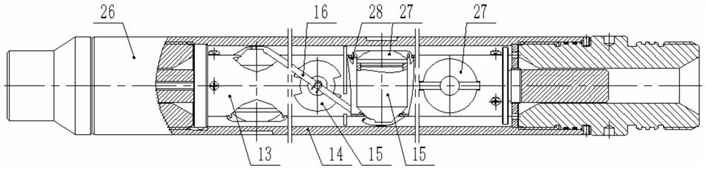
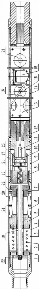
[0032] Such as figure 1 As shown, this embodiment includes a detonating mechanism 26, a gun body 14, a cartridge holder 13, a detonating cord 16 and a perforating charge 15. A firing pin 11 is arranged in the detonating mechanism 26. When detonating, the firing pin 11 slides downward under pressure , and then detonate the perforating charge 15 by detonating the detonating cord 16 . The above are the common structures in the existing pressure detonation type perforating devices, and will not be repeated here.

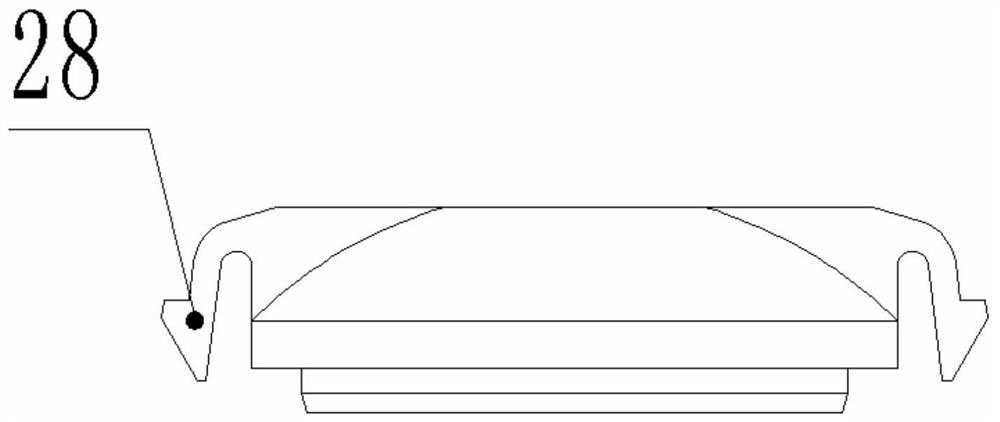
[0033] A major innovation of the present invention is that it also includes an energy release and expansion body 27, which exists independently of the perforating charge 15 and has no connection with the perforating charge 15. The energy release and expansion body 27 is installed in the perforation flick the head.

[0034] During specific implementation, the energy...


PUM


Abstract

The invention belongs to the field of oil field well completion construction technology equipment, and particularly relates to an energy releasing expansion perforation device. A detonation mechanism,a gun body, a gun carrier, a detonating cord and a perforating bullet are included. A firing pin is arranged in the detonation mechanism. During detonation, the firing pin downwards slides under theaction of pressure, and then the detonating cord is detonated to detonate the perforating bullet. An energy releasing expansion body is further included and arranged at the head of the perforating bullet. The energy releasing expansion body structurally comprises an energy releasing expansion body shell and a composite reagent with which the energy releasing expansion body shell is filled. When the perforating bullet is detonated, jet flow is conducted in a reclaimed hole way, vortex field attraction caused by high-speed jet flow can bring high-energy particles in the energy releasing expansion body into a perforating hole way, local scorching ignition is caused through gathering, colliding and interaction of the mist high-energy particles, transformation from detonation to spiral detonation is rapidly finished, then a hole way compaction layer influencing oil outflow is destroyed, and the volume of the hole way can be further increased.

Description

technical field [0001] The invention belongs to the field of oilfield well completion construction technology equipment, in particular to an energy-releasing and capacity-expanding perforating device. Background technique [0002] In the field of petroleum engineering, perforation is an important step in the completion of oil wells. When perforating, the perforating device equipped with perforating bullets is lowered to the predetermined position in the downhole through the tubing, and then the perforating device is pressed into the tubing string. The detonating mechanism within the embrasure device, thereby detonating the perforating charge. In the prior art, the perforating device has the following defects that need to be improved: 1. After the perforation of the existing perforating device is completed, a compaction layer will be formed on the inner wall of the perforation tunnel, and the existence of the compaction layer reduces the permeability of the formation , which...

Claims


Application Information

Patent Timeline
Patent Type & Authority Patents(China)
IPC IPC(8): E21B43/116E21B43/119E21B43/1185C06B33/02C06B33/12
CPCC06B33/02C06B33/12E21B43/116E21B43/1185E21B43/119
Inventor 禹栽星于德明徐文超宋波张国杰
Owner 大庆金祥寓科技有限公司
Why Eureka
Try Eureka