Intelligent plunger control device and method

A control device and control method technology, applied in pump control, earthwork drilling, mining fluid, etc., can solve problems such as production stoppage, cumbersome manual management work, and flooding, so as to overcome flooding and improve the efficiency of lifting and drainage Effect

Active Publication Date: 2020-05-22
XIAN SITAN INSTR
View PDF8 Cites 5 Cited by
  • Summary
  • Abstract
  • Description
  • Claims
  • Application Information

AI Technical Summary

Problems solved by technology

[0003] However, the existing plunger gas lift technology generally suffers from low lifting efficiency and cumbersome manual management work, which requires manual continuous inspection and adjustment of control parameters to achieve a better drainage effect. Even so, there are still many wells that will Flooded due to unreasonable system, reduced production or even stopped production

Method used


Image

  • Intelligent plunger control device and method
  • Intelligent plunger control device and method
  • Intelligent plunger control device and method

Examples


Embodiment 1

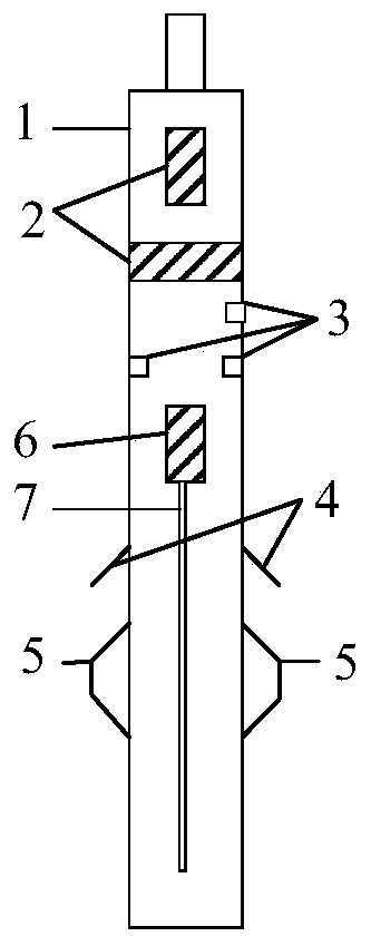
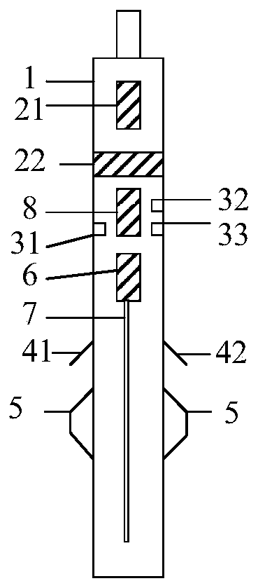
[0045] See figure 1 , 2 , figure 1 It is a schematic structural diagram of an intelligent plunger control device provided by an embodiment of the present invention, figure 2 It is a schematic structural diagram of another intelligent plunger control device provided by an embodiment of the present invention. This embodiment provides an intelligent plunger control device, which includes:

[0046] The ground controller, the smart plunger 1, the ground controller and the smart plunger 1 perform non-contact wireless communication with the smart plunger 1 through coil coupling, wherein,

[0047] The smart plunger 1 is provided with a charging communication module 2 and a sensor assembly 3. The outer wall of the smart plunger 1 is provided with a locking part 4 and a mechanical seal part 5. The mechanical seal part 5 is located below the locking part 4. The smart column The plug 1 is also provided with a motor 6 and a motor transmission rod 7 , the motor 6 is connected to the mo...

Embodiment 2

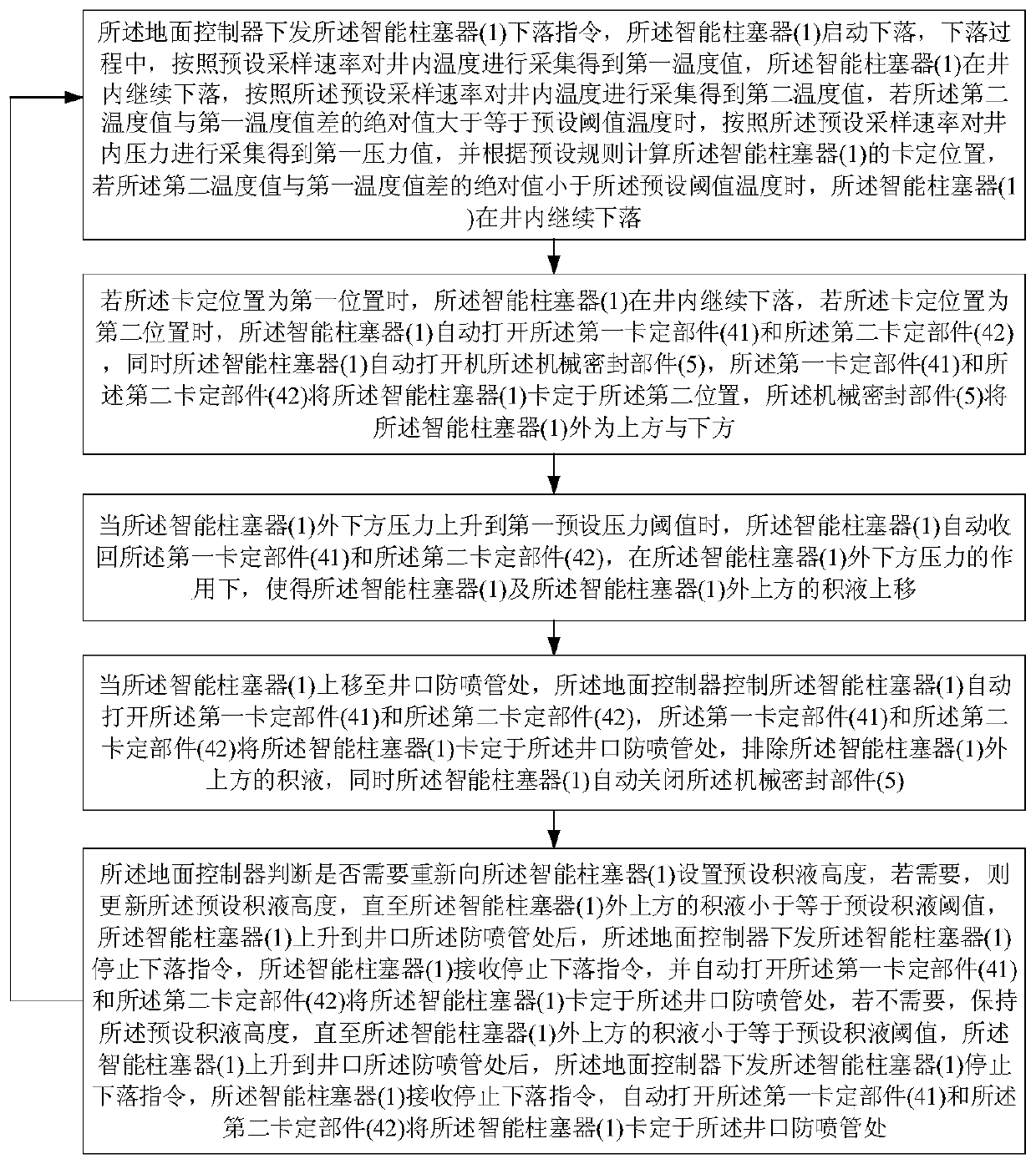
[0057] On the basis of the first embodiment above, please refer to Figure 4 , Figure 4 It is a schematic flowchart of an intelligent plunger control method provided by an embodiment of the present invention. This embodiment provides a smart plunger control method, which is implemented based on the smart plunger control device in Embodiment 1. Specifically, the smart plunger control method includes the following steps:

[0058] Step 1. The ground controller issues the whereabouts command of the smart plunger 1, and the smart plunger 1 starts to fall. During the fall, the temperature in the well is collected according to the preset sampling rate to obtain the first temperature value. The smart plunger 1 is in the The well continues to fall, and the temperature in the well is collected according to the preset sampling rate to obtain the second temperature value. If the absolute value of the difference between the second temperature value and the first temperature value is grea...


PUM


Abstract

The invention relates to an intelligent plunger control device and method. The intelligent plunger control device comprises a ground controller and an intelligent plunger device. Charging communication modules and sensor assemblies are arranged in the intelligent plunger device. Clamping fixing parts and mechanical sealing parts are arranged on the outer side wall of the intelligent plunger device, and the mechanical sealing parts are located below the clamping fixing parts. A motor and a motor transmission rod are further arranged in the intelligent plunger device, and the motor is connectedwith the motor transmission rod and further connected with the charging communication modules. According to the intelligent plunger control device, the automatic control process is formed by the cooperation of the ground controller and the intelligent plunger device, therefore, the problem that control parameters need to be continuously examined and adjusted by workers in the liquid drainage process is solved, the lifting liquid drainage efficiency is improved, and the automatic control process overcomes the defect that due to the fact that the artificial system arrangement is not reasonable,the water flooding problem and the production stop problem exist.

Description

technical field [0001] The invention belongs to the technical field of oil and gas well technology, and in particular relates to an intelligent plunger control device and a control method thereof. Background technique [0002] Fluid accumulation is inevitable during the production process of natural oil and gas wells. Especially in the middle and later stages of oil and gas well production, if the accumulated fluid is not discharged in time, the gas production of the oil and gas well will be greatly affected. The plunger gas lift technology is considered to be one of the optimal drainage gas recovery methods, and has been widely used in Southwest China, Changqing and other places. [0003] However, the existing plunger gas lift technology generally suffers from low lifting efficiency and cumbersome manual management work, which requires manual continuous inspection and adjustment of control parameters to achieve a better drainage effect. Even so, there are still many wells ...

Claims


Application Information

Patent Timeline
Patent Type & Authority Applications(China)
IPC IPC(8): E21B43/12E21B47/008E21B47/07E21B47/06E21B47/09E21B23/01E21B47/12F04B49/06F04B17/03F04B47/00
CPCE21B43/122E21B43/128E21B47/06E21B47/09E21B23/01E21B47/12F04B49/065F04B17/03F04B47/00Y02E10/10
Inventor 王崇峰周明刚杨琨王振华康学玺孙晓飞李晓朋
Owner XIAN SITAN INSTR
Why Eureka
Try Eureka