
An electrical device, a standby control circuit and a control method thereof

A technology for controlling circuits and electrical equipment, applied in computer control, program control, general control systems, etc., can solve problems such as increased standby power consumption, inability to turn on the power board, and inability to flexibly adjust the voltage value of the power-on trigger signal to ensure Effects of normal turn-on and reduced standby power consumption

Active Publication Date: 2021-12-28
SHENZHEN SKYWORTH DIGITAL TECH CO LTD
View PDF0 Cites 0 Cited by
  • Summary
  • Abstract
  • Description
  • Claims
  • Application Information

AI Technical Summary

Problems solved by technology

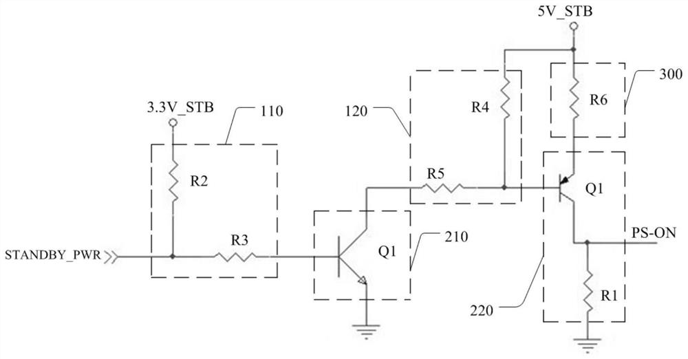
[0003] At the same time, when the resistance value of the pull-up resistor in the standby circuit increases, the standby power consumption will decrease, but the voltage value of the corresponding output power-on trigger signal will also decrease, which will cause the power board to fail to turn on; and when the pull-up resistor When the resistance value decreases, the voltage value of the power-on trigger signal will increase, but the standby power consumption will also increase accordingly, and the voltage value of the power-on trigger signal cannot be flexibly adjusted.

Method used


Image

  • An electrical device, a standby control circuit and a control method thereof
  • An electrical device, a standby control circuit and a control method thereof
  • An electrical device, a standby control circuit and a control method thereof

Examples


Embodiment Construction

[0024] The object of the present invention is to provide an electrical device, a standby control circuit and a control method thereof, which can effectively reduce the standby power consumption of the electrical device when the electrical device is in standby, and ensure that the power board can be turned on normally according to application requirements.

[0025] In order to make the object, technical solution and effect of the present invention more clear and definite, the present invention will be further described in detail below with reference to the accompanying drawings and examples. It should be understood that the specific embodiments described here are only used to explain the present invention, not to limit the present invention.

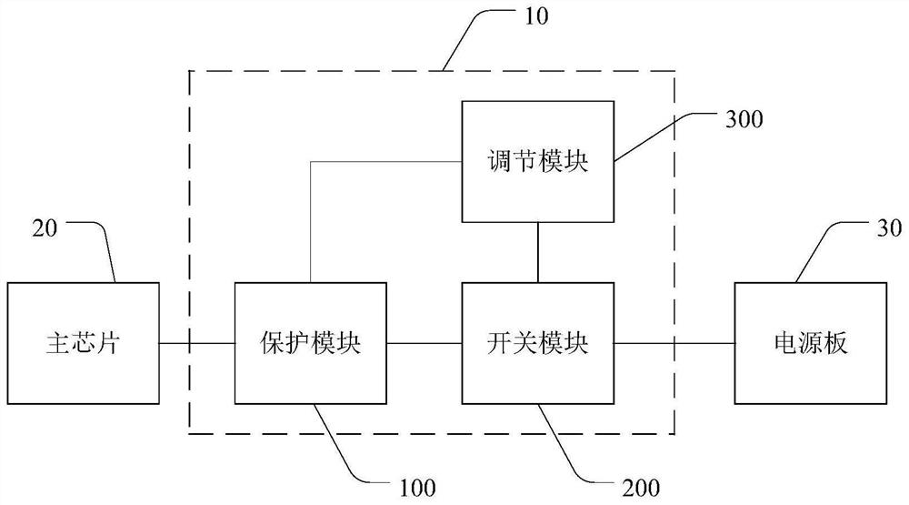
[0026] see figure 1 , the standby control circuit 10 provided by the present invention is respectively connected with the main chip 20 and the power supply board 30 of the electrical equipment, and the main chip 20 and the standby control...


PUM


Abstract

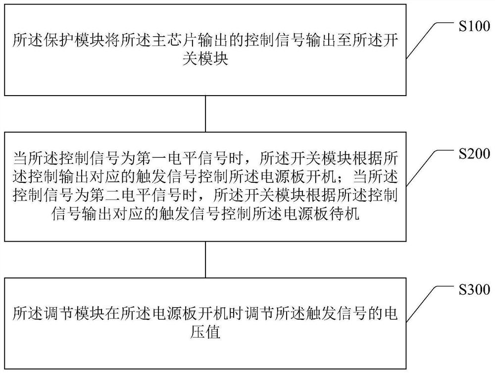
The invention discloses an electrical device, a standby control circuit and a control method thereof. The standby control circuit is respectively connected with a main chip and a power board of the electrical device, and includes a protection module, a switch module and an adjustment module; the protection module connects the The control signal output by the main chip is output to the switch module; when the control signal is a first level signal, the switch module outputs a corresponding trigger signal according to the control signal to control the power board to start; When the control signal is a second level signal, the switch module outputs a corresponding trigger signal according to the control signal to control the power board to stand by; the adjustment module adjusts the voltage of the trigger signal when the power board is turned on value, thereby effectively reducing the standby power consumption of electrical equipment during standby, and ensuring that the power board can be turned on normally according to application requirements.

Description

technical field [0001] The invention relates to the technical field of electrical circuits, in particular to an electrical device, a standby control circuit and a control method thereof. Background technique [0002] No matter whether the current standby control circuit is working or standby, the standby circuit itself will always generate a conduction current, which increases the standby power consumption of the product when it is in standby. [0003] At the same time, when the resistance value of the pull-up resistor in the standby circuit increases, the standby power consumption will decrease, but the voltage value of the corresponding output power-on trigger signal will also decrease, which will cause the power board to fail to turn on; and when the pull-up resistor When the resistance value of the power-on trigger signal decreases, the voltage value of the power-on trigger signal will increase, but the standby power consumption will also increase accordingly, and the vo...

Claims


Application Information

Patent Timeline
Patent Type & Authority Patents(China)
IPC IPC(8): G05B19/042
CPCG05B19/0423G05B2219/25257
Inventor 翁玉清田阳刘保
Owner SHENZHEN SKYWORTH DIGITAL TECH CO LTD
Learn More