Unlock instant, AI-driven research and patent intelligence for your innovation.

Method and device for dynamically calculating delay required for switching paths of link aggregation group

A technology for switching paths and path delays. It is applied in data exchange networks, digital transmission systems, electrical components, etc., and can solve problems such as retransmission over time and inability to adapt to delay values.

Inactive Publication Date: 2020-05-22
INSPUR SUZHOU INTELLIGENT TECH CO LTD
View PDF9 Cites 0 Cited by
  • Summary
  • Abstract
  • Description
  • Claims
  • Application Information

AI Technical Summary

Problems solved by technology

[0007] The fixed delay value of the existing technology cannot adapt to various network conditions. If the delay is too small, packet reordering will still occur. If the delay is too large, the destination host has not received the next packet for too long and will cause timeout retransmission. Therefore, the fixed delay value is not The best solution to this problem

Method used


Image

  • Method and device for dynamically calculating delay required for switching paths of link aggregation group
  • Method and device for dynamically calculating delay required for switching paths of link aggregation group
  • Method and device for dynamically calculating delay required for switching paths of link aggregation group

Examples


Embodiment approach 1

[0044] Such as image 3 As shown, this embodiment provides an apparatus for dynamically calculating the delay required for link aggregation group switching paths, including a central control unit and a switch.

[0045] The central control unit (Controller): regularly initiates path delay searches to each switch, obtains the path delay time required by each switch to reach other switches through its different link group members, and saves all path delay times.

[0046] Switch (Switch): When switching the packet flow on different link group members, search the corresponding path delay time from the central control unit, and set the required delay according to the searched path delay time.

[0047] For the central control unit, it includes a path delay acquisition module and a path delay storage module, wherein:

[0048] Path delay acquisition module: complete the regular initiation of path delay search to each switch, and obtain the path delay time required by each switch to re...

Embodiment 2

[0063] Such as Figure 4 shown, combined with Figure 5 As shown in the schematic diagram of information transmission, this embodiment provides a method for dynamically calculating the delay required for link aggregation group switching paths, including the following steps:

[0064] Timely obtain the path delay time required by each switch to reach other switches through their different link group members, and save all path delay times;

[0065] When the switch switches packet streams on different link group members, it searches for the corresponding path delay time, and sets the required delay according to the searched path delay time.

[0066] Specifically, the central control unit regularly initiates a path delay search to each switch, obtains the path delay time required by each switch to reach other switches through their different link group members, and saves all the path delay times;

[0067] When the switch switches packet flows on different link group members, the ...


PUM


Abstract

The invention discloses a method and a device for dynamically calculating delay required for switching paths of a link aggregation group. The method comprises: a central control unit regularly initiating path delay search to each switch, obtaining path delay time required by each switch to reach other switches through respective different link group members, and storing all the path delay time; and when the switch switches the packet flows on different link group members, searching the corresponding path delay time from the central control unit, and setting the required delay according to thesearched path delay time. According to the scheme, the problem of packet rearrangement caused by fixed delay adopted for path switching of the link aggregation group in the prior art is solved, and the path delay error obtained according to actual detection of the current environment is adopted, so that the problem of packet rearrangement does not exist, and the network transmission efficiency isnot greatly reduced due to path switching.

Description

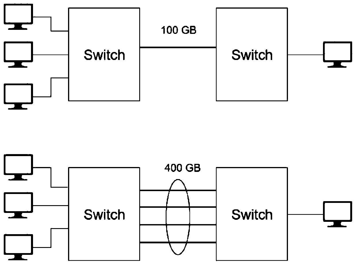
technical field [0001] The invention relates to the field of switching paths of link aggregation groups of switches, in particular to a method and device for dynamically calculating the delay required for switching paths of link aggregation groups. Background technique [0002] Link aggregation (Port Channel), refers to the aggregation of multiple physical ports together to form a logical port, in order to achieve the load balance of outbound / incoming traffic throughput among member ports. The member port from which the packet is sent to the peer switch. Such as figure 1 As shown, after setting four ports to join the link aggregation, the bandwidth of the link aggregation can be increased to 400GB. [0003] Such as figure 2 As shown, when the objects of the aggregated links are different switches, there is a great chance of packet timing errors during path switching, because the delays of different paths are different, which leads to the abnormal sequence of packets arri...

Claims


Application Information

Patent Timeline
Patent Type & Authority Applications(China)
IPC IPC(8): H04L12/709H04L12/26H04L45/243
CPCH04L45/245H04L43/0852
Inventor 卢彥呈
Owner INSPUR SUZHOU INTELLIGENT TECH CO LTD