Intermediate joint protection structure for power supply sealed cable

A technology of intermediate joints and protective structures, applied in cable joints, cable entry sealing devices, etc., can solve the problems of persistent protection of difficult internal cables, single-layer shells are easily affected and damaged by the external environment, etc., so as to reduce the pulling force. force, reducing mass, reducing the effect of transmission

Inactive Publication Date: 2021-11-19
邹升
View PDF0 Cites 0 Cited by
  • Summary
  • Abstract
  • Description
  • Claims
  • Application Information

AI Technical Summary

Problems solved by technology

[0005] Aiming at the deficiencies of the prior art, the present invention provides an intermediate joint protection structure of a power supply sealed cable, which solves the problem that most of the existing cable intermediate joint protection structures use single-layer equipment for connection protection, and its own single-layer shell It is easy to be affected by the external environment and damaged by external objects, and it is difficult to permanently protect the internal cables.

Method used


Image

  • Intermediate joint protection structure for power supply sealed cable
  • Intermediate joint protection structure for power supply sealed cable
  • Intermediate joint protection structure for power supply sealed cable

Examples


Embodiment 1

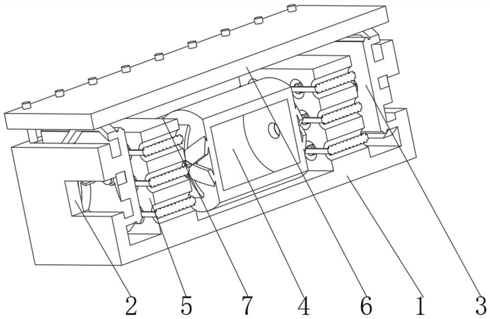
[0038] see Figure 1-3 , the present invention provides a technical solution: an intermediate joint protection structure for a power supply sealed cable, specifically comprising:

[0039]Box body 1, the box body 1 has a square shell, and an access hole 2 opened in the middle of the outer walls on both sides of the square shell, and a sealing device 3 installed on the inner walls of both sides of the square shell, and installed in the inner cavity of the square shell The joint protection device 4 in the middle position, and the winding device 5 installed in the inner cavity of the square housing and between the sealing device 3 and the joint protection device 4, and the cover 6 installed on the top of the square housing, through the box body 1 and The setting of the joint protection device 4 provides double-layer protection for the cable joints to prevent external objects from directly affecting the safety of the joint protection device 4. At the same time, the double-layer pro...

Embodiment 2

[0048] see Figure 1-4 On the basis of Embodiment 1, the present invention provides a technical solution: the sealing device 3 includes:

[0049] Limiting plate 31, the limiting plate 31 has a rectangular plate body, and an auxiliary hole 32 provided in the middle of the rectangular plate body, and a sealing rubber ring 33 installed on the outer surface of the rectangular plate body, and is arranged on the rectangular plate body close to the box body 1 the hexagonal movable rod frame 34 on one side, and the positioning struts 35 installed on both sides of the inner surface of the hexagonal movable rod frame 34, and the lock ring installed on the middle position of the positioning strut 35 away from the side movable rod frame 34 plate 36. Through the setting of the hexagonal movable rod frame 34 and the positioning strut 35, the separation of the components is realized, and the bonding between the components and the outer skin of the cable after the cable is locked is avoided,...

Embodiment 3

[0053] see Figure 1-5 , on the basis of Embodiment 1 and Embodiment 2, the present invention provides a technical solution: the winding device 5 includes:

[0054] Mounting block 51, the mounting block 51 has a square main body, and a through-hole groove 52 provided on the outer wall of the square main body, and a winding rod 53 installed in the inner cavity of the through-hole groove 52, and a threaded winding groove provided on the outer surface of the winding rod 53 54, and is installed on the fixed strip 55 that wraps around bar 53 two ends. Through the design of the threaded winding groove 54 and the winding rod 53, the cables are surrounded, and the friction between them is increased by using the spiral, so as to avoid the pulling force of the cable from causing the inner core and the outer protective layer of the cable to be separated, and at the same time prevent the pulling force from being transmitted to the joint to prevent unraveling of the joints.

[0055] The ...


PUM


Abstract

The invention discloses an intermediate joint protection structure for a power supply sealed cable. The structure specifically comprises a box body, sealing devices which are disposed on the inner walls of two sides of a square housing, a joint protection device which is disposed in the middle of the inner cavity of the square housing and a winding device which is arranged in the inner cavity of the square housing and located between the sealing device and the joint protection device. The joint protection device comprises a protection box, arc-shaped clamping plates arranged at the top and the bottom of the outer surface of the barrel-shaped body and reverse arc plates arranged on the sides, away from the barrel-shaped body, of the arc-shaped clamping plates. The invention relates to the technical field of cables. Through the arrangement of the box body and the joint protection device, the cable joint is subjected to double-layer protection, the safety of the joint protection device is prevented from being directly influenced by an external object, meanwhile, an interlayer of the cavity is formed through the double-layer protection, the resistance to the external environment temperature change is enhanced, and the application range of the equipment is widened.

Description

technical field [0001] The invention relates to the technical field of cables, in particular to an intermediate joint protection structure of a power supply sealed cable. Background technique [0002] Power cables are cables used to transmit and distribute electric energy. They are composed of one or more wires. Power cables are often used in urban underground power grids, power station lead-out lines, internal power supply in industrial and mining enterprises, and underwater transmission lines across rivers and seas. In the line, the proportion of cables is gradually increasing. Power cables are cable products used to transmit and distribute high-power electric energy in the backbone lines of power systems, and sealed cables are a kind of cables with high sealing performance. They are often used outdoors. It is used in the environment; when the high-voltage cable is laid for a long length, it is necessary to use the cable intermediate joint for connection, and the connectio...

Claims


Application Information

Patent Timeline
Patent Type & Authority Applications(China)
IPC IPC(8): H02G15/10H02G15/013
CPCH02G15/10H02G15/013
Inventor 邹升
Owner 邹升
Why Eureka
Try Eureka