Rotary dewatering and cleaning tool for electric mop
A technology of spin dehydration and cleaning tools, which is applied to cleaning equipment, cleaning machinery, carpet cleaning, etc., and can solve the problems that the mop bucket cannot be operated separately, immersed in water, and inconvenient to use.
- Summary
- Abstract
- Description
- Claims
- Application Information
AI Technical Summary
Problems solved by technology
Method used
Image
Examples
Embodiment 1
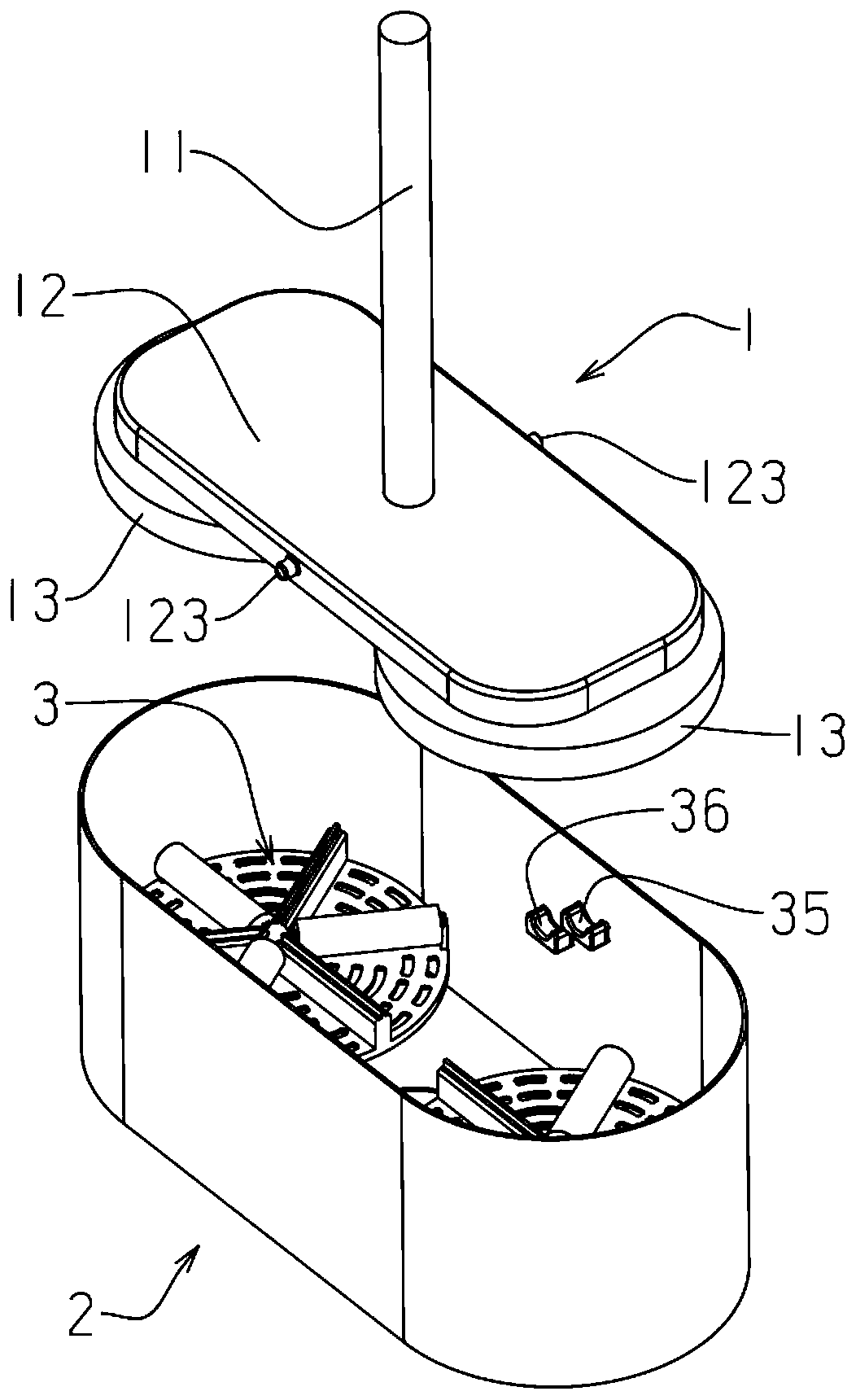
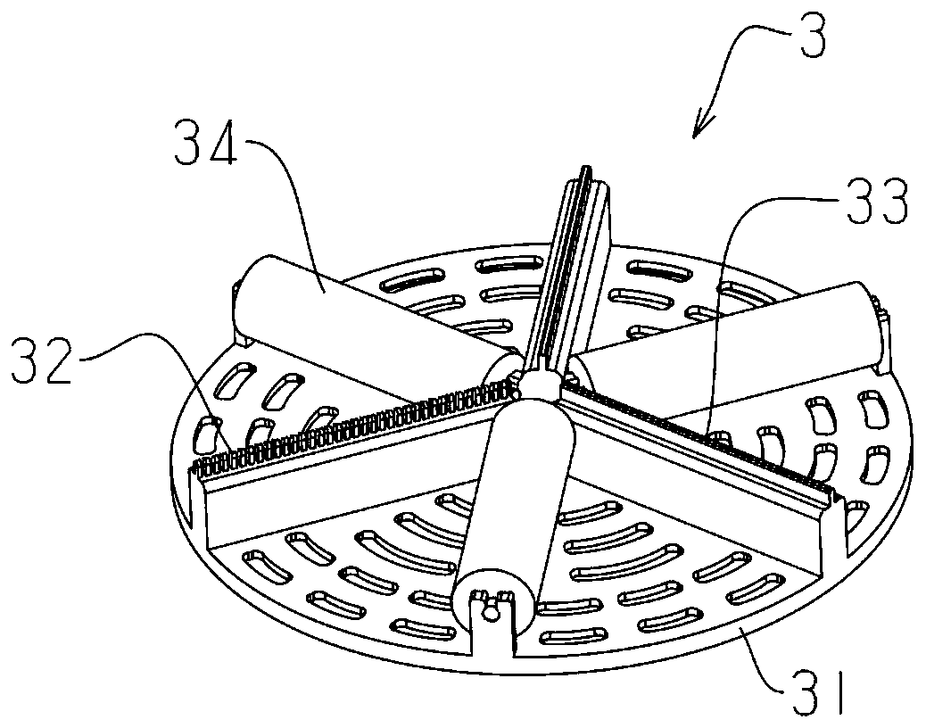
[0059] An electric mop spin dehydration cleaning tool, such as figure 1 Shown: comprise electric mop 1 and mop barrel 2, described electric mop comprises mop bar 11 and mop head 12, and described mop head is provided with wiping object 13, is provided with in the described mop bucket and is used for cleaning described wiping object The scrubbing part 3 and the support portion supporting the electric mop, the electric mop leans against the support portion and has a high position and a low position;
[0060] When the electric mop is at a low position, the wiper is in contact with the scrubbing part and is cleaned by the rotation of the electric mop; when the electric mop is at a high position, the wiper is away from the scrubbing part and passed Spin dry to dehydrate.
[0061] The type and form of the electric mop of the present invention are not limited, and may be a rotary head type flat mop, a rotary belt mop and / or a horizontal roller type rotary mop.
[0062] In addition,...
Embodiment 2
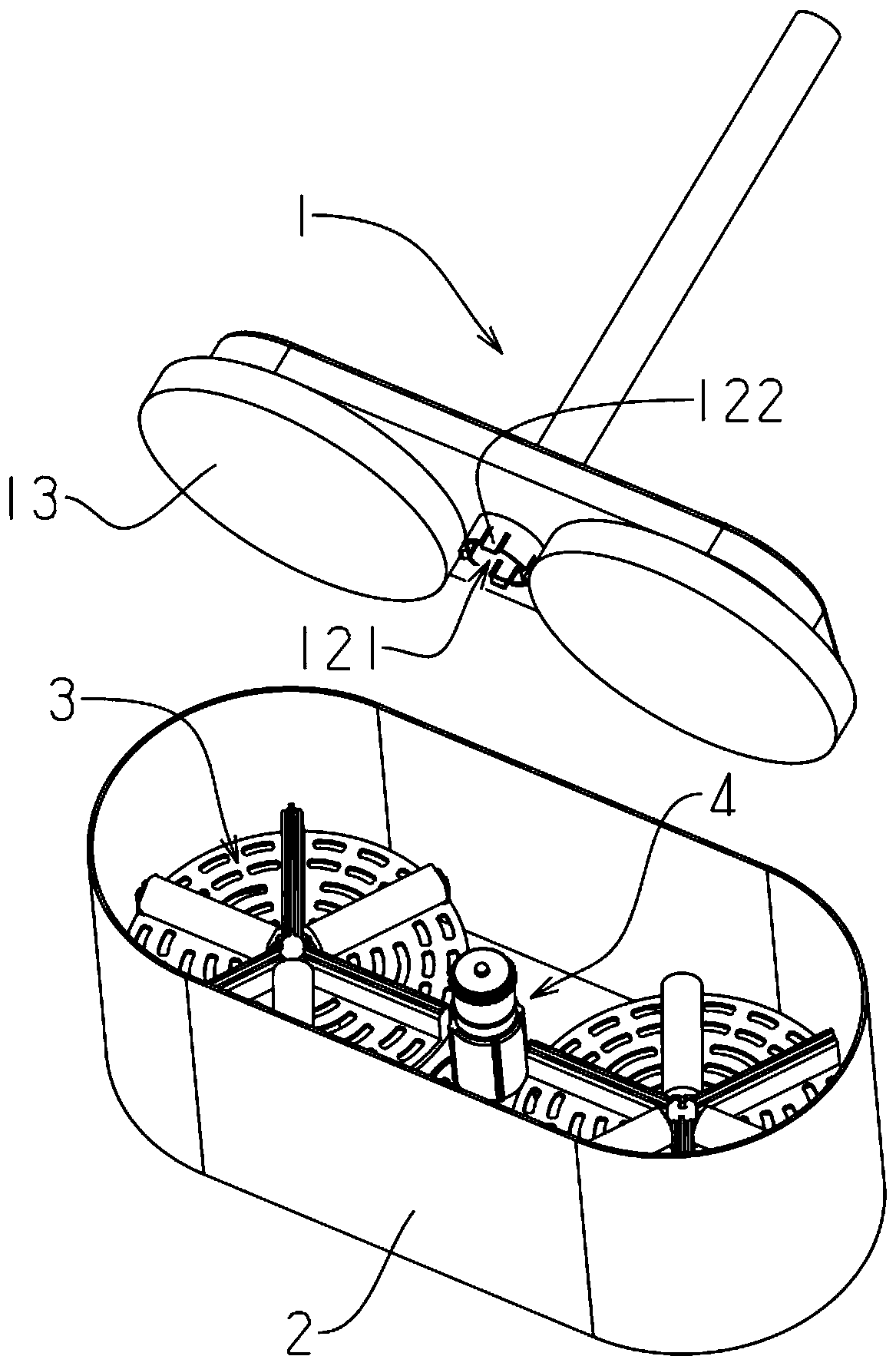
[0074] The difference between this embodiment and Embodiment 1 is that the electric mop is positioned at a high position and a low position, such as image 3 As shown: a lifting device 4 is also provided, and the support part is arranged on the lifting device, and the support part can be located at the high position or at the low position through the lifting device, so that the support part against the support The electric mop at the top has the high position and the low position.
[0075] Such as Figure 4 to Figure 7 As shown: the lifting device includes a fixed column 41, a moving tube 42 and a positioning rod 43, the fixed column is fixedly connected to the mop bucket, the moving tube is sleeved outside the fixed column, and the positioning rod passes through the mop bucket. Move the tube and insert it into the socket at the center of the fixed column, and the positioning rod is relatively locked against the fixed column, and the upper end of the positioning rod is the su...
Embodiment 3
[0091] The difference between embodiment 3 and embodiment 2 lies in the structure of the lifting device, such as Figure 11 to Figure 14 As shown: the lifting device includes a fixed seat 45 and a lifting column 46, and the upper part of the lifting column is the supporting part;
[0092] The fixed seat is fixedly connected to the mop bucket, the lifting column is connected through the sleeve with the fixed seat, and the lifting column can slide along its axial direction and rotate along its circumferential direction, and the side wall of the fixed seat High-level steps 451 are provided, and the high-level steps are evenly distributed along the circumference of the side wall. Low-level steps 452 are also provided between each adjacent high-level steps. Steps or positioning blocks 461 of the lower steps;
[0093] The mop head has a positioning hole 121 into which the upper end of the moving tube can be inserted, and a clamping structure 122 capable of clamping the moving tube ...
PUM
 Abstract
Description
Claims
Application Information
 - R&D
- Intellectual Property
- Life Sciences
- Materials
- Tech Scout
- Unparalleled Data Quality
- Higher Quality Content
- 60% Fewer Hallucinations
Browse by: Latest US Patents, China's latest patents, Technical Efficacy Thesaurus, Application Domain, Technology Topic, Popular Technical Reports.
© 2025 PatSnap. All rights reserved.Legal|Privacy policy|Modern Slavery Act Transparency Statement|Sitemap|About US| Contact US: help@patsnap.com


