Centrifugal mechanism and in vitro detection analyzer

A centrifugal mechanism and centrifugal motor technology, applied in the centrifugal field, can solve problems such as equipment downtime, working system failure, and difficult positioning of centrifugal cups, and achieve the effect of avoiding failure

Pending Publication Date: 2020-05-26
SHANGHAI UPPER BIO TECH PHARMA
View PDF0 Cites 3 Cited by
  • Summary
  • Abstract
  • Description
  • Claims
  • Application Information

AI Technical Summary

Problems solved by technology

Due to the existence of the spring, the structure such as the centrifugal disc is on a floating mechanism. As the centrifuge works longer and longer, the spring may undergo permanent deformation and the centrifugal disc cannot maintain a horizontal state, which will make the centrifuge Difficult to position the centrifuge cups on the plate accurately
Once the position deviation of the centrifuge cup exceeds a certain range, the mechanical arm used to automatically grab the centrifuge cup will not be able to accurately load and unload the centrifuge cup, which may lead to the failure of the entire working system and equipment downtime

Method used


Image

  • Centrifugal mechanism and in vitro detection analyzer
  • Centrifugal mechanism and in vitro detection analyzer
  • Centrifugal mechanism and in vitro detection analyzer

Examples


Embodiment Construction

[0041] Exemplary embodiments of the present invention are described below with reference to the accompanying drawings. It should be understood that these specific descriptions are only used to teach those skilled in the art how to implement the present invention, and are not intended to exhaust all feasible modes of the present invention, nor are they used to limit the protection scope of the present invention.

[0042] The "connection" mentioned in the present invention includes both direct connection and indirect connection through intermediate members.

[0043] The following is based on Figure 1 to Figure 6 A specific embodiment of the centrifugal mechanism according to the present invention will be described in detail.

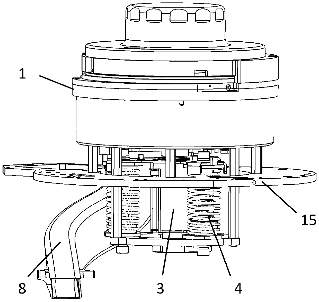
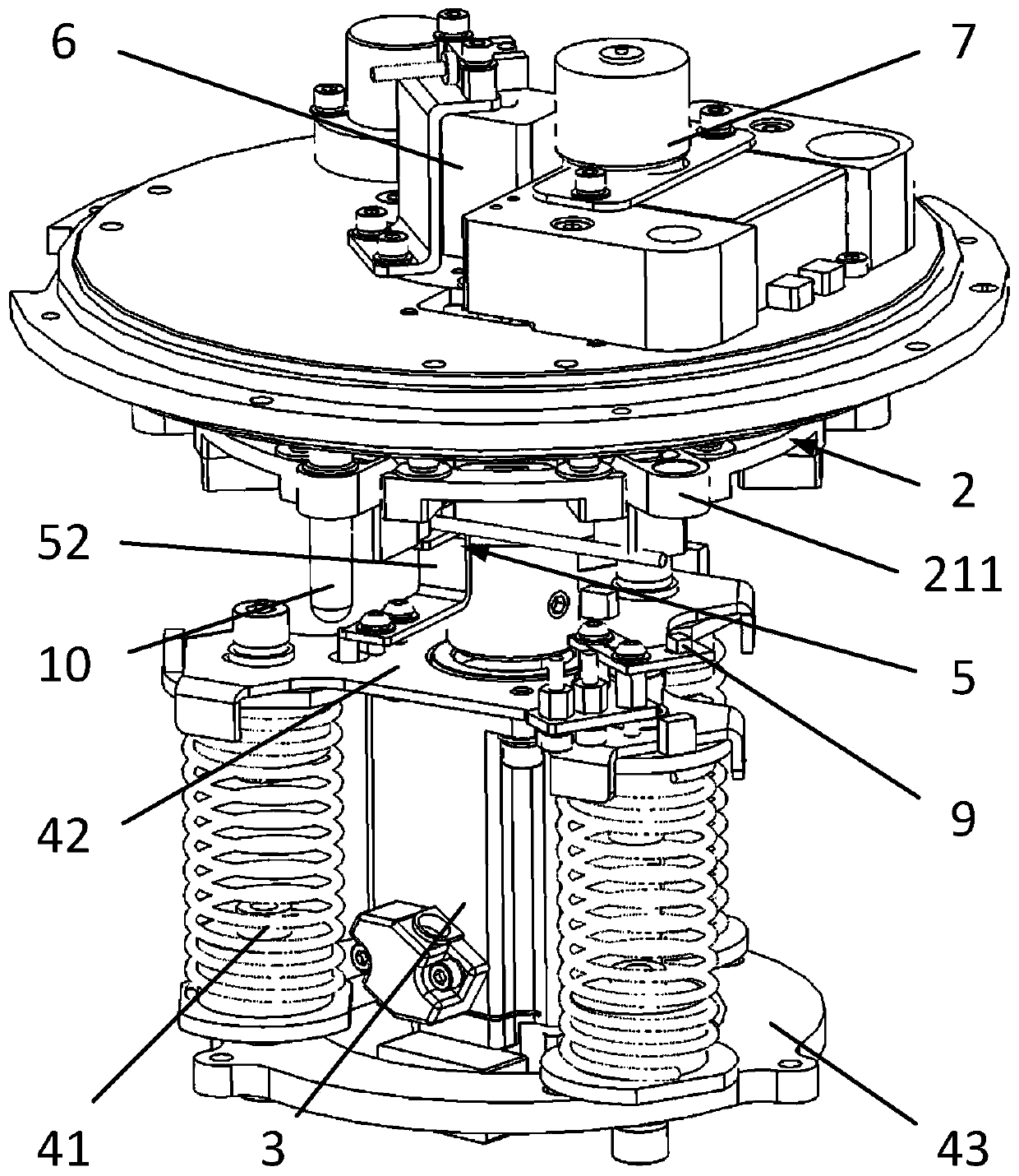
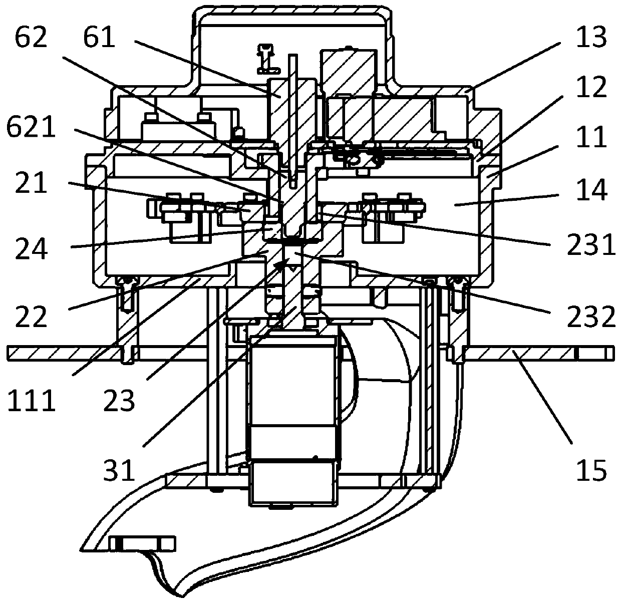
[0044] In this embodiment, if figure 1 and figure 2 As shown, the centrifugal mechanism includes a housing 1, a centrifugal disc assembly 2, a centrifugal motor 3, a vibration damping mechanism 4, a circumferential positioning mechanism 5, a horizonta...


PUM


Abstract

The invention relates to a centrifugal mechanism and an in vitro detection analyzer. The centrifugal mechanism comprises a centrifugal disc assembly, a circumferential positioning mechanism and a horizontal positioning mechanism, a positioning hole is formed in the centrifugal assembly in the vertical direction, the circumferential positioning mechanism comprises a circumferential detection sensor, the circumferential detection sensor is used for detecting the circumferential position of the centrifugal disc assembly, thus the centrifugal disc assembly is circumferentially positioned, the horizontal positioning mechanism comprise a positioning driving mechanism and a positioning piece which are connected in a transmission mode, the positioning driving mechanism can drive the positioning piece to move in the vertical direction, so that the positioning piece is inserted into the positioning hole, and thus the centrifugal disc assembly is horizontally positioned in a radial-centered mode.According to the centrifugal mechanism, a centrifugal cup can be accurately positioned.

Description

technical field [0001] The invention relates to the technical field of centrifugation, in particular to a centrifugal mechanism and an in vitro detection analyzer comprising the centrifugal mechanism. Background technique [0002] The centrifuge is the equipment that must be used in chemiluminescent in vitro diagnostic equipment. The centrifuge needs to rotate at a high speed to separate the serum and blood cells, which will inevitably generate large vibrations. In order to eliminate vibration, it is usually necessary to use springs for vibration damping. Due to the existence of the spring, the structure such as the centrifugal disc is on a floating mechanism. As the centrifuge works longer and longer, the spring may undergo permanent deformation and the centrifugal disc cannot maintain a horizontal state, which will make the centrifuge The centrifuge cups on the plate are difficult to position accurately. Once the position deviation of the centrifuge cup exceeds a certai...

Claims


Application Information

Patent Timeline
Patent Type & Authority Applications(China)
IPC IPC(8): B04B5/04B04B11/04G01N35/00
CPCB04B5/0407B04B11/04B04B2011/046G01N35/00G01N2035/00495
Inventor 戴文东陈琦赵建平
Owner SHANGHAI UPPER BIO TECH PHARMA
Why Eureka
Try Eureka