Supercharge Your Innovation With Domain-Expert AI Agents!

Large diameter polarized wire grid winding device

A technology of polarized wire grid and winding device, which is used in transportation and packaging, thin material handling, transportation of filamentous materials, etc., can solve personal and equipment safety accidents, imprints on the surface of materials, and cannot meet multiple windings, etc. problems, to prevent wire breakage or wire slack, improve control accuracy and speed, and improve reliability and safety

Active Publication Date: 2021-11-09
CHINA ELECTRONICS TECH GRP NO 39 RES INST
View PDF13 Cites 0 Cited by
  • Summary
  • Abstract
  • Description
  • Claims
  • Application Information

AI Technical Summary

Problems solved by technology

In addition, the original technical scheme uses nylon material for the round tube, which has low hardness. After repeated use, there will be marks on the surface of the material, which cannot meet the requirements of multiple windings and must be changed.
[0010] 2. In the original technical solution, the rotating mechanism is exposed, which is acceptable for small wire grid winding devices. For large wire grid winding devices, the exposed rotating mechanism is obviously unsafe during the working process, which is likely to cause personal and equipment safety accidents
Therefore, the equipment must be closed and isolated

Method used


Image

  • Large diameter polarized wire grid winding device
  • Large diameter polarized wire grid winding device
  • Large diameter polarized wire grid winding device

Examples


Embodiment Construction

[0061] Embodiments of the present invention are described in detail below, and the embodiments are exemplary and intended to explain the present invention, but should not be construed as limiting the present invention.

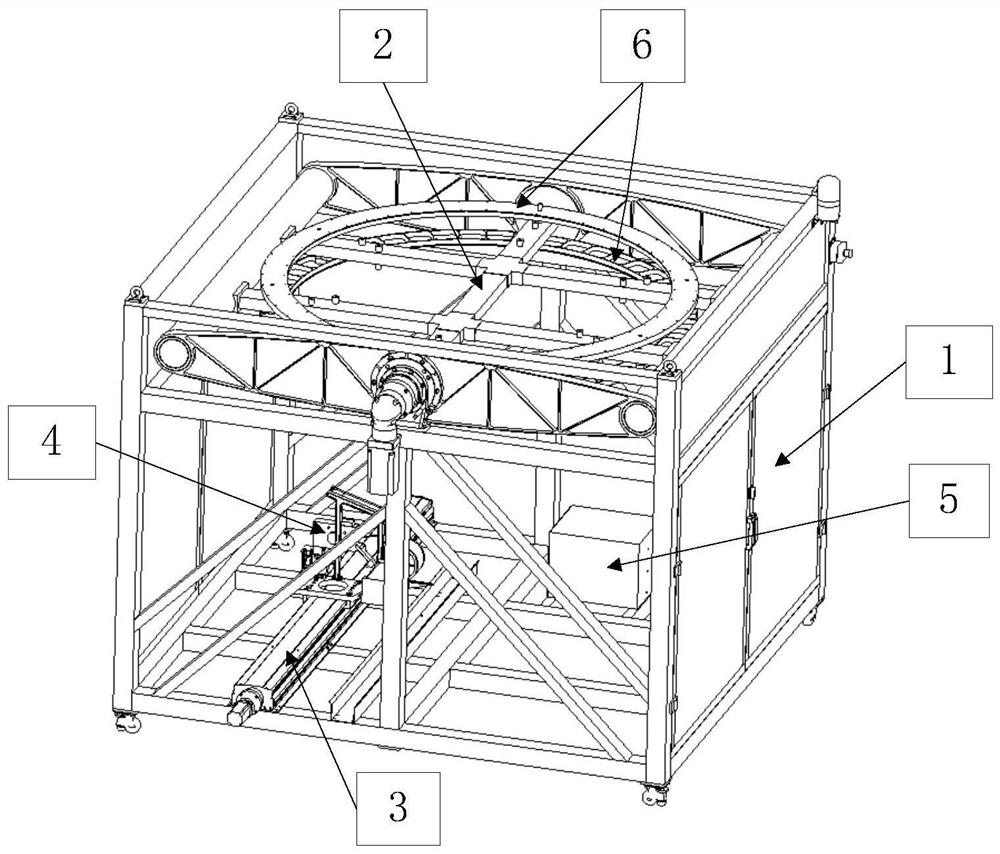
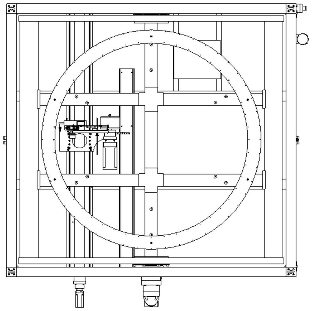
[0062] The structural schematic diagram of the polarized wire grid winding device in this embodiment is as follows figure 1 shown. It mainly includes working platform, winding mechanism, wire arranging mechanism, pay-off mechanism, control unit, etc. Its working principle is that the uniform rotational motion of the winding mechanism and the linear motion of the wire arranging mechanism synthesize the equidistant spiral motion of the metal wire, thus forming Equidistant linear array.

[0063] The working platform provides the installation interface of the winding mechanism, the cable arrangement mechanism and the control box.

[0064] The winding mechanism is located in the upper center of the working platform, and is installed on the working platform throug...


PUM


Abstract

The present invention proposes a large-diameter polarized wire grid winding device, which includes a working platform, a winding mechanism, a wire arrangement mechanism, a wire release mechanism, and a control unit; the winding mechanism can rotate around the rotation axis, and the platform movement direction of the wire arrangement mechanism is in line with the The rotation axis of the winding mechanism is parallel; the pay-off mechanism is installed on the platform of the wire-discharging mechanism, and the metal wire can be released from the pay-off mechanism with a constant tension and wound on the winding mechanism with a wire grid ring installed; the control unit controls the rotation The frame speed, the moving speed of the cable mechanism platform and the pay-off speed of the pay-off mechanism. The pay-off mechanism in the present invention is an active pay-off system with variable wire speed and constant tension, including a wire reel, a motor drive device for the pay-off mechanism, a crimping rod, a double guide wheel tensioner, a shaft angle sensor, a guide wheel, and a tension controller. , Wire rod; through the joint action of electric drive device, double guide wheel tensioner, and shaft angle sensor, the closed-loop control of the pay-off speed can be realized to prevent wire breakage or wire slack.

Description

technical field [0001] The invention relates to a large diameter polarization wire grid winding device. Background technique [0002] As a low-loss polarization separator, the polarization wire grid is a quasi-optical device used for polarization separation of electromagnetic waves. As a low-loss polarizer, it can be used in microwave, millimeter wave, submillimeter It is widely used in the far-infrared band. my country's "Gaofen-1" satellite, Fengyun-3 "microwave hygrometer" and the "full polarization microwave radiometer calibration source" developed by the Microwave Remote Sensing Department of the National Space Center have important applications. [0003] The main body of the polarized wire grid consists of a series of equally spaced, vertically or horizontally arranged metal wires. Ideally, when the vertical polarization direction of the incident electromagnetic wave is parallel to the polarized wire grid, the vertically polarized electromagnetic wave is reflected an...

Claims


Application Information

Patent Timeline
Patent Type & Authority Patents(China)
IPC IPC(8): B65H54/28B65H59/38B65H75/20
CPCB65H54/2833B65H59/387B65H75/20B65H2701/36
Inventor 李果万人民杨永涛李姣李娜赵泓滨李彬吴利英雷静袁岁维郭良
Owner CHINA ELECTRONICS TECH GRP NO 39 RES INST
Features
  • R&D
  • Intellectual Property
  • Life Sciences
  • Materials
  • Tech Scout
  • Unparalleled Data Quality
  • Higher Quality Content
  • 60% Fewer Hallucinations
Learn More