Building decorative board hoisting device capable of reducing wear rate

A technology for architectural decoration and hoisting equipment, which is applied in the direction of construction, building structure, lighting and heating equipment, etc. It can solve the problems of increasing the damage rate of the board, falling of the decorative board, and cumbersome fixing process, so as to facilitate the observation of the surrounding environment, The effect of improving safety

Inactive Publication Date: 2020-05-29
刘明涛
View PDF5 Cites 0 Cited by
  • Summary
  • Abstract
  • Description
  • Claims
  • Application Information

AI Technical Summary

Problems solved by technology

[0002] At present, most of the interior and exterior walls of buildings will be installed with decorative panels to achieve a certain purpose of heat insulation, noise reduction and moisture resistance. Decorative panels usually need to be hoisted and transported to high altitudes for installation.

Method used


Image

  • Building decorative board hoisting device capable of reducing wear rate
  • Building decorative board hoisting device capable of reducing wear rate
  • Building decorative board hoisting device capable of reducing wear rate

Examples


Embodiment 1

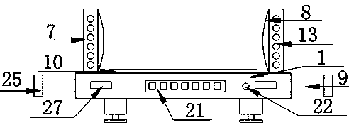
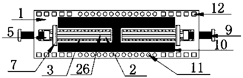
[0031] Embodiment one, such as Figure 1-6 As shown, according to an embodiment of the present invention, a hoisting device for building decorative panels capable of reducing the wear rate includes a base 1, a protective pad 10 is provided at the center of the top of the base 1, and the top sides of the base 1 are located at the The middle part of the protective pad 10 is provided with a chute 2, and the inner middle part of the chute 2 is provided with a guide rod 26. Both sides are provided with slide rails 3, and a motor 5 is provided in the chute 2, and a plurality of pulleys 4 are provided at the bottom of the motor 5, and the pulleys 4 cooperate with the slide rails 3, and the A motor shaft 9 is provided at the center of one side of the motor 5, and the outer surface of the motor shaft 9 is provided with threads, and the connection between the base 1 and the motor shaft 9 is provided with a circular threaded hole. The threads on the outer surface of the motor shaft 9 co...

Embodiment 2

[0032] Embodiment two, such as Figure 5 As shown, there is a circular through hole at the center of the bottom of the load bearing block 16, the load bearing block 16 is slidingly connected with the support column 19 through the circular through hole, the guide rod 26 is made of high alloy steel material, The bottom of the motor 5 is provided with a circular through hole matching with the guide rod 26 , and the guide rod 26 is slidably connected to the motor 5 through the through hole.

Embodiment 3

[0033] Embodiment three, such as figure 1 As shown, the suspension ring 27 is a semi-circular structure, the suspension ring 27 is made of low-alloy steel material, the top plate 18, the support column 19 and the bottom plate 20 are all made of high-alloy steel material, The side of the motor shaft 9 away from the motor 5 is provided with a limiting block 25 , the limiting block 25 is a cylindrical structure, and the diameter of the limiting block 25 is larger than the diameter of the threaded hole on the side of the base 1 .


PUM

PropertyMeasurementUnit
Thicknessaaaaaaaaaa

Abstract

The invention discloses a building decorative board hoisting device capable of reducing the wear rate. The building decorative board hoisting device comprises a base, wherein a protective pad is arranged at the center of the top of the base; sliding grooves are formed in the two sides of the top of the base and positioned in the middle of the protective pad; guide rods are arranged in the middlesof the sliding grooves; the two ends of each guide rod are welded and fixed to the inner wall of the corresponding sliding groove; sliding rails are arranged on the two side edges of the bottom of theinterior of each sliding groove; motors are arranged in the sliding grooves; a plurality of pulleys are arranged at the bottoms of the motors; the pulleys are matched with the sliding rails; motor shafts are arranged at the centers of one of the sides of the motors; threads are arranged on the outer surfaces of the motor shafts; and round threaded holes are formed in the joints of the base and the motor shafts. The building decorative board hoisting device has the beneficial effects that a plurality of illuminating lamps are arranged at the top of the base, so that workers can work at night conveniently, meanwhile, the safety of the workers is improved, and the workers can observe the surrounding environment conveniently.

Description

technical field [0001] The invention relates to the technical field of construction equipment, in particular to a hoisting device for building decorative panels that can reduce the wear rate. Background technique [0002] At present, most of the interior and exterior walls of buildings will be installed with decorative panels to achieve a certain purpose of heat insulation, noise reduction and moisture resistance. Decorative panels usually need to be hoisted and transported to high altitudes for installation. The equipment fixing process of the decorative panel is relatively cumbersome. During the lifting process, the decorative panel is likely to fall or be squeezed and worn between the panels, which not only increases the damage rate of the panel, but also poses a threat to the life safety of the staff. [0003] To sum up, how to provide a hoisting device for building decorative panels that can reduce the wear rate is an urgent technical problem to be solved at present. ...

Claims


Application Information

Patent Timeline
IPC IPC(8): B66C1/44B66C15/00B66C15/06E04G21/16F21V33/00F21Y115/10
CPCB66C1/442B66C15/00B66C15/065E04G21/167F21V33/006F21Y2115/10
Inventor 刘明涛林继红王泽丰
Owner 刘明涛
Why Eureka
Try Eureka