Electric butterfly valve

An electric butterfly valve and valve body technology, applied in valve details, valve devices, engine components, etc., can solve the problem of large torque of the butterfly valve, which is not conducive to the long-term use of the butterfly valve, and achieve the effects of reducing power, prolonging service life, and reducing opening torque.

Inactive Publication Date: 2020-05-29
邵延荣
View PDF9 Cites 0 Cited by
  • Summary
  • Abstract
  • Description
  • Claims
  • Application Information

AI Technical Summary

Problems solved by technology

With the development of industry, the application of electric butterfly valve also increases; when the electric butterfly valve is in use, there is generally a large pressure difference between the two sides of the flap, so a large torque is required when the butterfly valve is opened, but When the butterfly valve opens to a certain angle, the required motor torque decreases due to the decrease in pressure difference, so in order to meet the starting torque, a larger power motor is required, and the larger torque when the butterfly valve is opened is not conducive to the long-term use of the butterfly valve

Method used


Image

  • Electric butterfly valve
  • Electric butterfly valve
  • Electric butterfly valve

Examples


Embodiment Construction

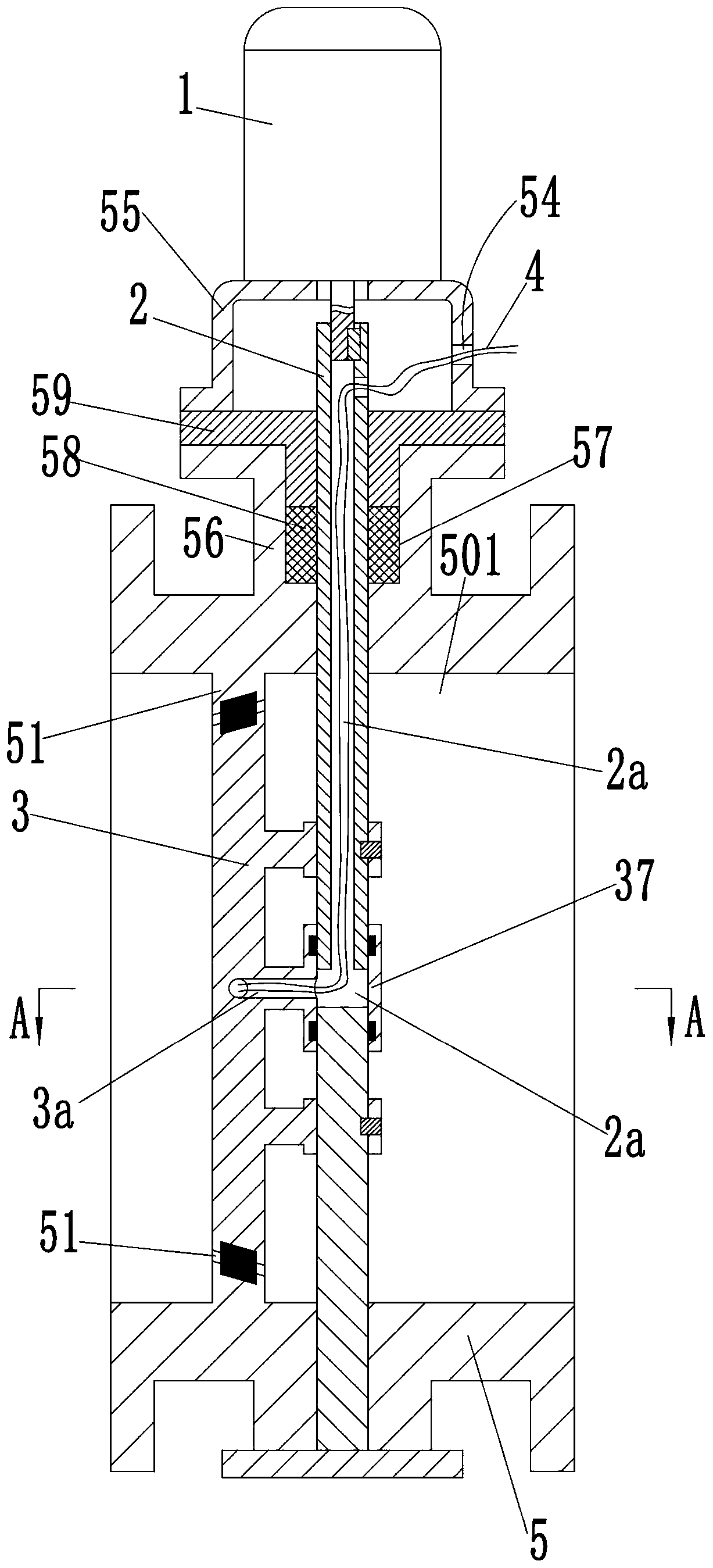
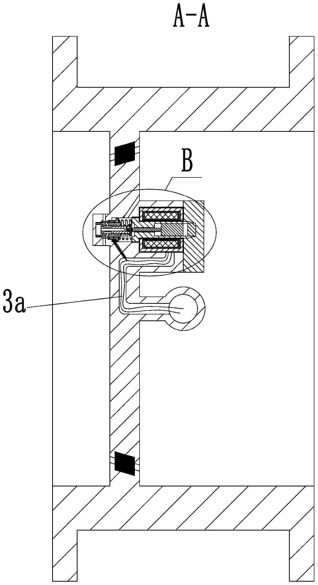
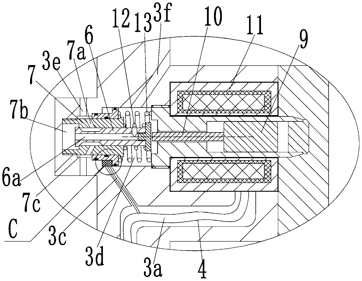
[0021] see Figure 1-5 As shown in the figure, an electric butterfly valve includes a valve body 5, and the valve body 5 is provided with a channel 501 penetrating left and right, the left end of the channel 501 is the inlet, and the right end is the outlet; baffle plate 51, the baffle plate 51 is provided with a valve port 52; the valve body 5 is rotatably connected with a rotating shaft 2, and the rotating shaft 2 is fixedly installed with a flap 3 for controlling the opening and closing of the valve port 52; the valve The outer side of the body 5 is fixedly installed with a motor 1 for driving the rotating shaft 2 to rotate; the right side of the flap 3 is provided with a first valve hole 31 and a second valve hole 32 in sequence to the left, and the flap 3 is provided with a There is a first through hole 3e for communicating the inlet and the second valve hole 32; a valve sleeve 7 is fixedly installed in the second valve hole 32, and a magnetic guide sleeve 91 is fixedly i...


PUM


Abstract

The invention discloses an electric butterfly valve, which comprises a valve body. The valve body is internally provided with a channel penetrating through from left to right; a baffle plate is arranged on the inner side wall of the channel, and is provided with a valve port; the valve body is internally and rotatably connected with a rotating shaft, and the rotating shaft is fixedly provided witha flap plate; the outer side of the valve body is fixedly provided with a motor; the flap plate is provided with a first valve hole and a second valve hole, the second valve hole is internally and fixedly provided with a valve sleeve, and a magnetic guide sleeve is fixedly arranged on the opening of the right end of the first valve hole; the valve sleeve is internally provided with a sliding holepenetrating through from left to right; the sliding hole is internally and slidably connected with a valve core; a spring seat is fixedly arranged at the right end of the valve core, and the valve core is connected with a first spring in a sleeved mode; the right end of the magnetic guide sleeve is slidably connected with a moving iron, and the magnetic guide sleeve is provided with a push rod; acoil is arranged at the side face of the outer circumference of the magnetic guide sleeve; before the electric butterfly valve is opened, mediums at the two ends of the butterfly valve are in communication in advance to reduce a pressure difference between the two sides, and thus power of the motor does not increase suddenly when the flap plate is controlled to rotate.

Description

technical field [0001] The invention belongs to the field of pipeline valves, in particular to an electric butterfly valve. Background technique [0002] Butterfly valve, also known as flap valve, is a kind of regulating valve with simple structure, which mainly plays the role of cutting off and throttling on the pipeline. The butterfly valve opening and closing part is a disc-shaped flap that rotates around its own axis in the valve body to achieve the purpose of opening and closing or adjustment. With the development of the industry, the use of electric butterfly valves has also increased; when the electric butterfly valve is in use, there will generally be a large pressure difference on both sides of the flap, so a larger torque will be required when the butterfly valve is opened, but When the butterfly valve is opened to a certain angle, the motor torque required by the pressure difference decreases, so in order to meet the starting torque, a larger power motor needs to...

Claims


Application Information

Patent Timeline
Patent Type & Authority Applications(China)
IPC IPC(8): F16K31/06
CPCF16K31/0655F16K31/0675
Inventor 邵延荣其他发明人请求不公开姓名
Owner 邵延荣
Why Eureka
Try Eureka