Microporous heater structure

A heater and microporous technology, applied in heating methods, heating elements, heating element materials, etc., can solve the problems of potential safety hazards, large power consumption, heavy weight, etc., and achieve light weight, safe use, and high heating efficiency. Effect

Active Publication Date: 2020-05-29
杭州慈源科技有限公司
View PDF26 Cites 1 Cited by
  • Summary
  • Abstract
  • Description
  • Claims
  • Application Information

AI Technical Summary

Problems solved by technology

[0003] In order to solve the problems of heavy weight, high power consumption and potential safety hazards in the indoor air heater in the prior art, the present invention provides a microporous heater structure with high heating efficiency, light weight and safe use

Method used


Image

  • Microporous heater structure
  • Microporous heater structure
  • Microporous heater structure

Examples


Embodiment Construction

[0024] The present invention will be further described below in conjunction with accompanying drawing and specific embodiment:

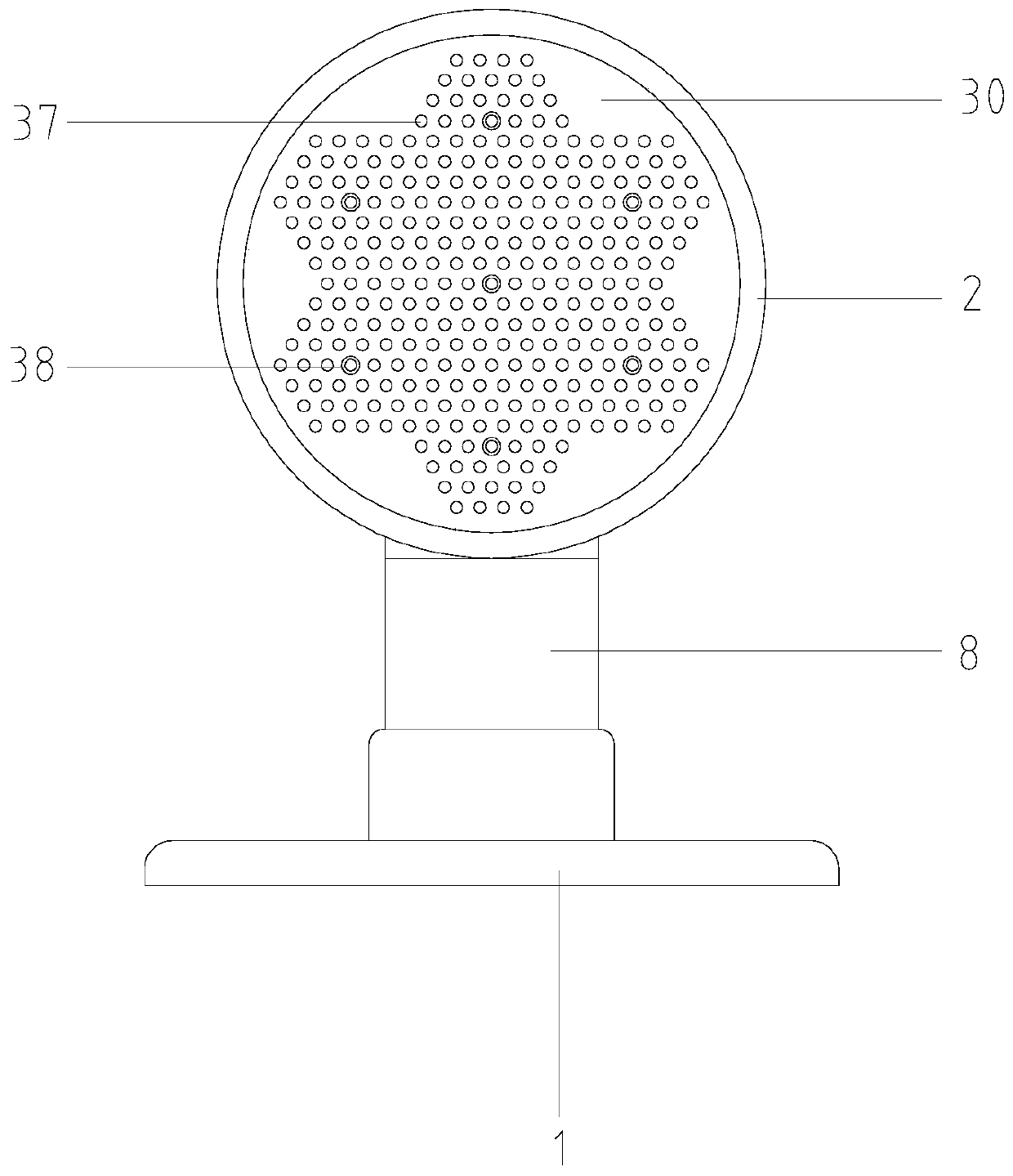
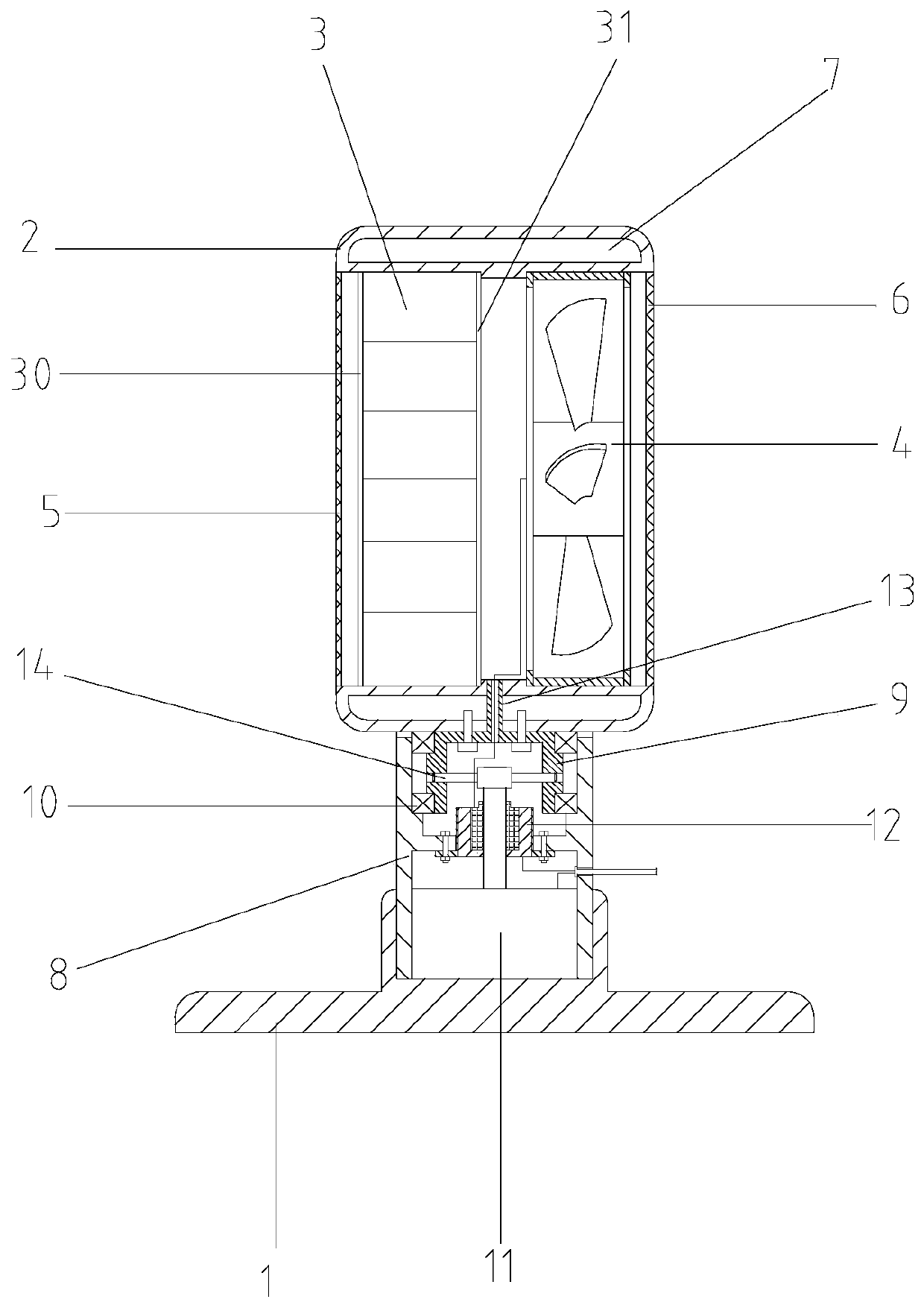
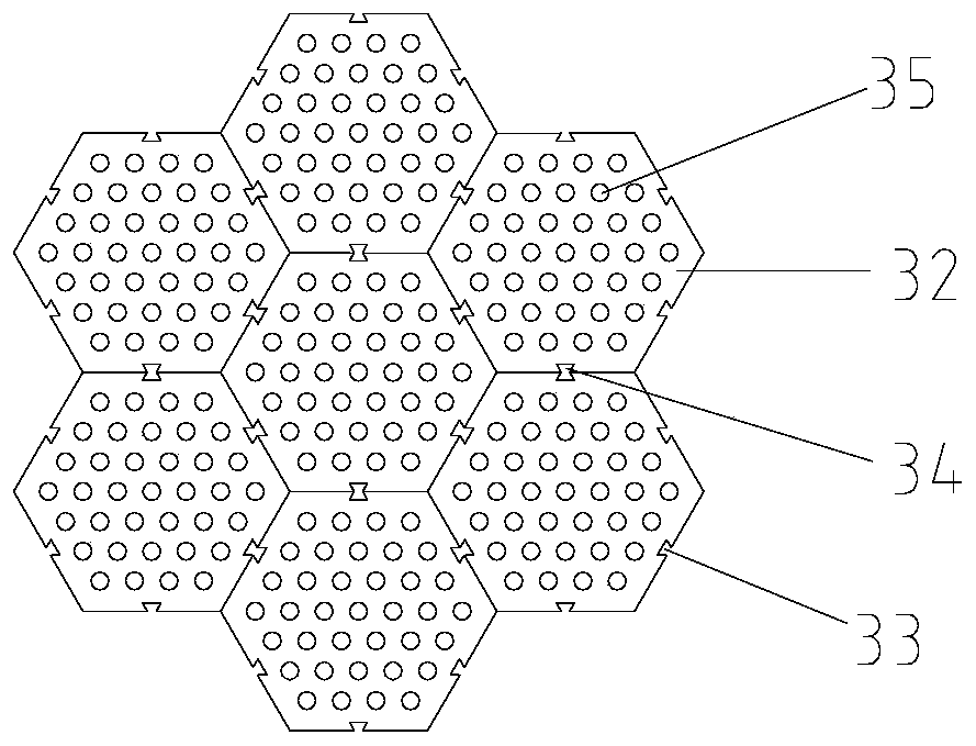
[0025] Such as figure 1 , figure 2 , image 3 and Figure 4 The structure of a microporous heater shown includes a base 1 and a shell 2 arranged on the upper end of the base. The shell 2 is provided with a heater body 3. The heater body 3 includes a front electrode plate 30, a rear electrode plate 31, and a Some ceramic membrane substrates 32 between the front electrode plate and the rear electrode plate, micropores are distributed in the ceramic membrane substrates 32, and graphene powder is filled in the micropores, and the ceramic membrane substrates 32 are columnar. The ceramic membrane substrates in this embodiment 32 is in the shape of a hexagonal column, and each side of the ceramic membrane substrate 32 is provided with a dovetail connection groove 33, and the dovetail connection grooves 33 on the sides where two adjacent ceramic membrane...


PUM

PropertyMeasurementUnit
Apertureaaaaaaaaaa
Granularityaaaaaaaaaa
Pore diameteraaaaaaaaaa

Abstract

The invention relates to the technical field of heaters, and discloses a microporous heater structure. The microporous heater structure comprises a base and a shell arranged at the upper end of the base, a heater body is arranged in the shell and comprises a front electrode plate, a rear electrode plate and a plurality of ceramic membrane substrates, micropores are distributed in the ceramic membrane substrates and filled with graphene powder, the ceramic membrane substrates are each in a column shape, a plurality of heating through holes are evenly distributed in the two ends of each ceramicmembrane substrate, graphene coatings are arranged on the end faces of the ceramic membrane substrates and the inner walls of the heating through holes, the front electrode plate is electrically connected with the graphene coatings at the front ends of the ceramic membrane substrates, the rear electrode plate is electrically connected with the graphene coatings at the rear ends of the ceramic membrane substrates, receding through holes corresponding to the heating through holes one to one are formed in the front electrode plate and the rear electrode plate, a fan is arranged in the rear end ofthe shell, a front grid plate is arranged at the front end of the shell, and a rear grid plate is arranged at the rear end of the shell. The microporous heater structure has the beneficial effects ofbeing high in heating efficiency, low in weight and safe in using.

Description

technical field [0001] The invention relates to the technical field of heaters, in particular to a microporous heater structure. Background technique [0002] In the cold winter, in order to increase the indoor temperature, the air conditioner can be used for heating. However, in some small indoor places without air conditioning, people will heat the room through a separate heater, such as oil tincture, which has the flexibility to use However, the oil tincture is very heavy, and the medium oil is used for heat exchange inside. During the heating process, the pipeline is prone to rupture and the high-temperature oil will flow out, causing great safety hazards; The hot air blown by the hair dryer is close, the power consumption is large, and the heating efficiency is low. Contents of the invention [0003] In order to solve the problems of heavy weight, high power consumption and potential safety hazards in the indoor air heater in the prior art, the present invention prov...

Claims


Application Information

Patent Timeline
IPC IPC(8): F24D13/02H05B3/14H05B3/06
CPCF24D13/02H05B3/145H05B3/06H05B3/008F24D2200/08
Inventor 王宝根姚美琴陈会云
Owner 杭州慈源科技有限公司
Why Eureka
Try Eureka