Laser radar ranging method and device, laser radar and storage medium
A technology of laser radar and distance measuring device, which is applied in the direction of measuring device, electromagnetic wave re-radiation, radio wave measurement system, etc., and can solve the problems of external small interference objects, equipment stray light interference, etc.
- Summary
- Abstract
- Description
- Claims
- Application Information
AI Technical Summary
Problems solved by technology
Method used
Image
Examples
Embodiment 1
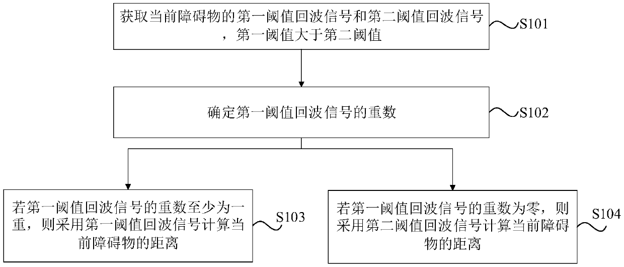
[0080] figure 1 The flow chart of the ranging method of the laser radar provided by Embodiment 1 of the present invention, such as figure 1 As shown, the laser radar ranging method provided in this embodiment is executed by the laser radar ranging device, and the laser radar ranging device is integrated in the laser radar, then the laser radar ranging provided in this embodiment The method includes the following steps.
[0081] Step 101, acquiring a first threshold echo signal and a second threshold echo signal of a current obstacle, the first threshold being greater than the second threshold.
[0082] Specifically, in this embodiment, the way to obtain the first threshold echo signal and the second threshold echo signal may be: the laser radar emits a laser signal to the obstacle; receives the echo optical signal returned by the obstacle, and undergoes photoelectric conversion, Amplify, and conduct time discrimination with the first threshold to obtain the first threshold e...
Embodiment 2
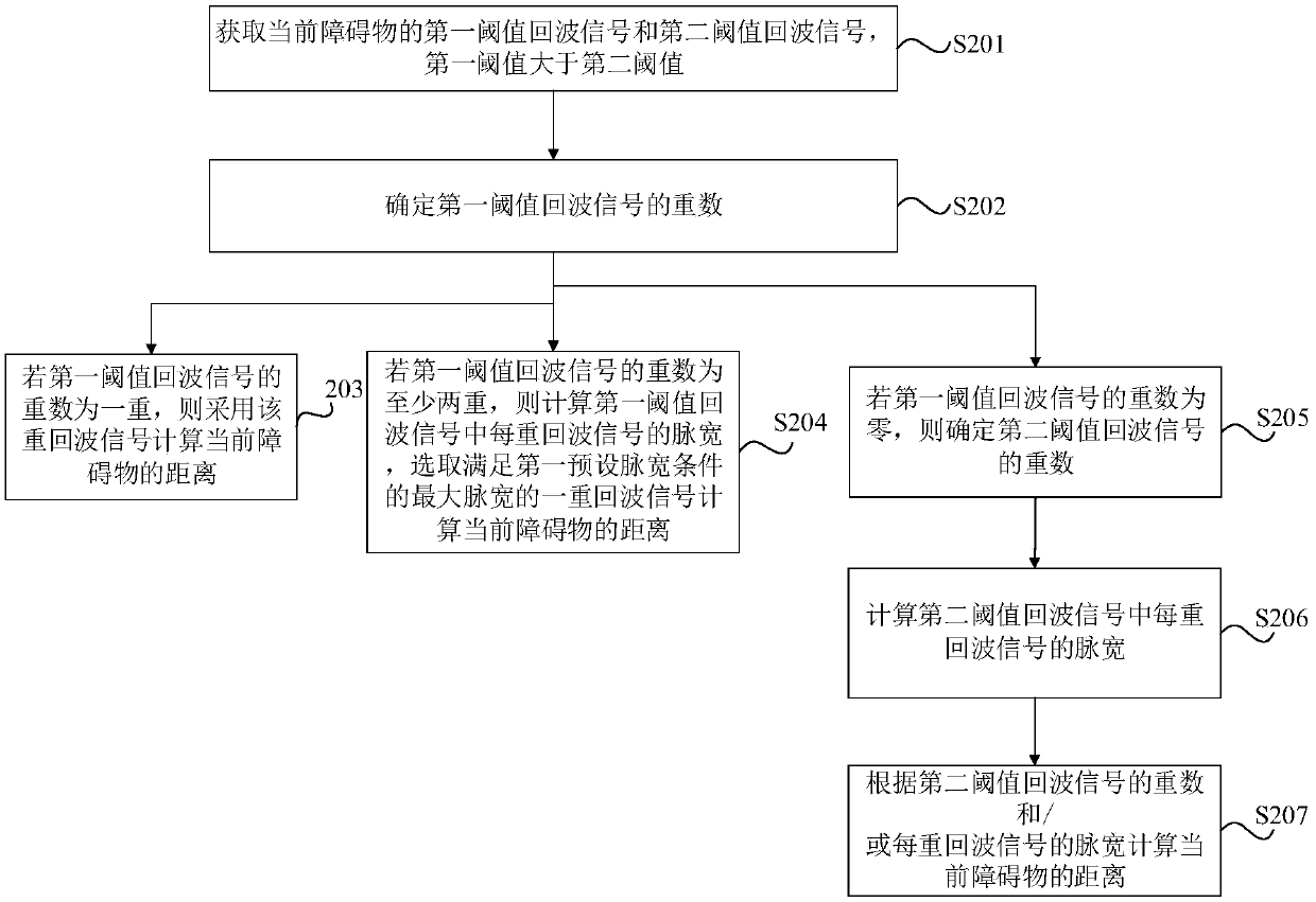
[0093] figure 2 The flow chart of the ranging method of the laser radar provided in Embodiment 2 of the present invention, such as figure 2 As shown, the laser radar ranging method provided in this embodiment is based on the laser radar ranging method provided in Embodiment 1 of the present invention, and steps 102-step 104 are further refined, then the present embodiment provides The ranging method of lidar includes the following steps.
[0094] Step 201, acquiring a first threshold echo signal and a second threshold echo signal of a current obstacle, the first threshold being greater than the second threshold.
[0095] In this embodiment, the implementation manner of step 201 is the same as the implementation manner of step 101 of the lidar ranging method provided in Embodiment 1 of the present invention, and will not be repeated here.
[0096] Step 202, determining the multiplicity of the first threshold echo signal.
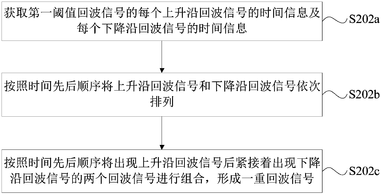
[0097] Further, in this embodiment, image 3 It i...
Embodiment 3
[0153] Figure 10 A schematic structural diagram of the distance measuring device of the laser radar provided in Embodiment 3 of the present invention, as shown in Figure 10 As shown, the lidar ranging device provided in this embodiment includes: an echo signal acquisition unit 1001 , a first multiplicity determination unit 1002 , a first distance calculation unit 1003 , and a second distance calculation unit 1004 .
[0154] Wherein, the echo signal acquiring unit 1001 is configured to acquire a first threshold echo signal and a second threshold echo signal of the current obstacle, and the first threshold is greater than the second threshold.
[0155] The first multiplicity determining unit 1002 is configured to determine the multiplicity of the first threshold echo signal.
[0156] The first distance calculation unit 1003 is configured to use the first threshold echo signal to calculate the current obstacle distance if the multiplicity of the first threshold echo signal is ...
PUM
 Abstract
Description
Claims
Application Information
 - R&D
- Intellectual Property
- Life Sciences
- Materials
- Tech Scout
- Unparalleled Data Quality
- Higher Quality Content
- 60% Fewer Hallucinations
Browse by: Latest US Patents, China's latest patents, Technical Efficacy Thesaurus, Application Domain, Technology Topic, Popular Technical Reports.
© 2025 PatSnap. All rights reserved.Legal|Privacy policy|Modern Slavery Act Transparency Statement|Sitemap|About US| Contact US: help@patsnap.com


